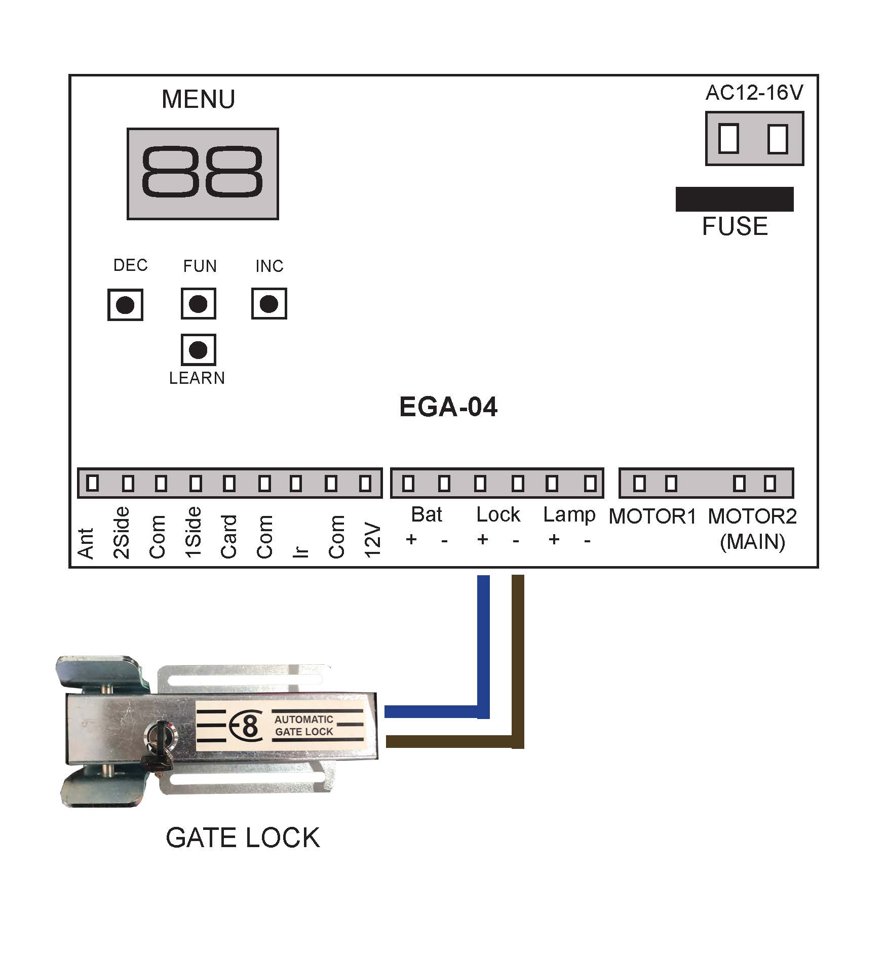
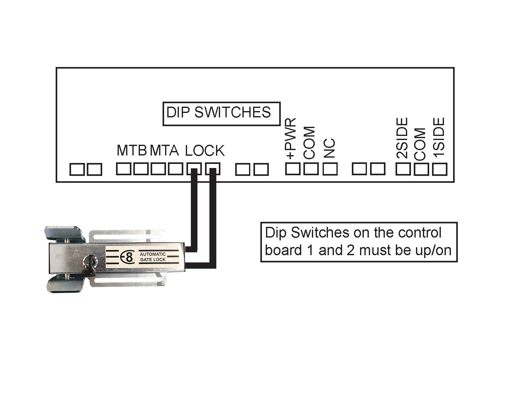
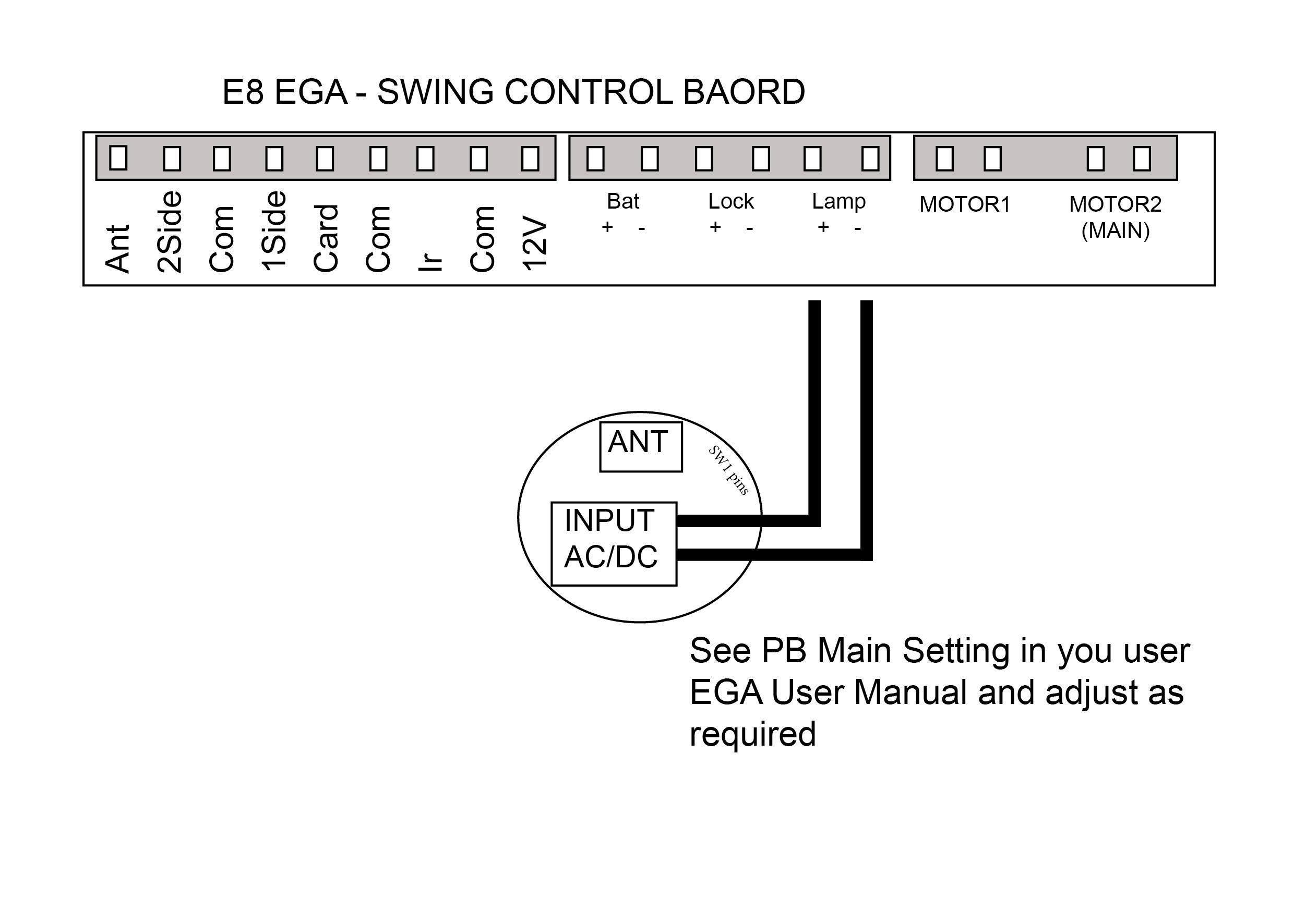
This setting is for Dual Swing gates. You can adjust the opening/closing delay between the two motors. This is required if you have an electric gate lock connected to the control board or if you require Motor 2 to open first and Motor 1 to close first. You can set this from 0 seconds (open and close at the same time) up to 8 seconds. Factory setting is 2 seconds and is recommended even if a gate lock is not installed.
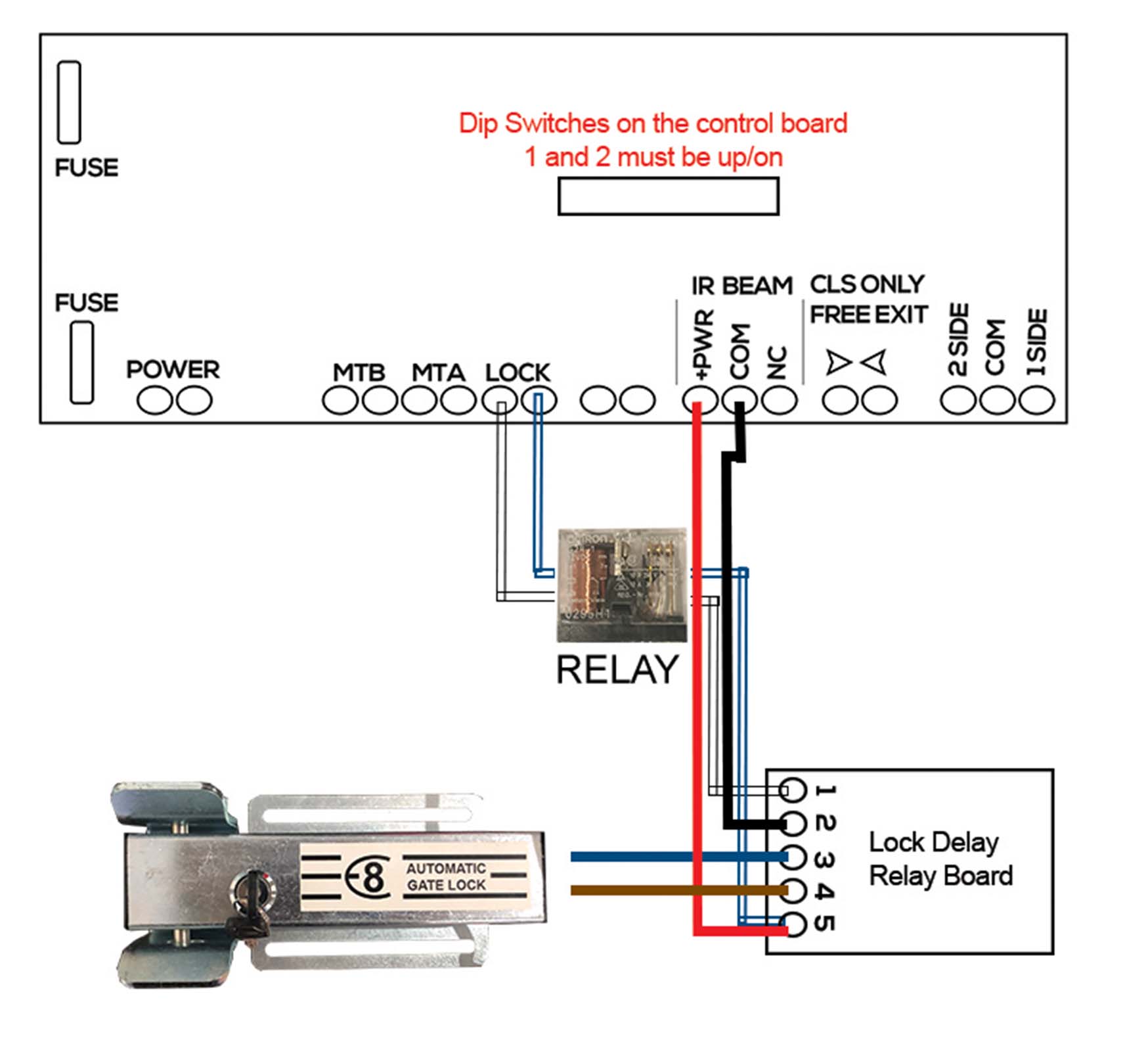
This setting allows you to adjust the output to you optional electric gate lock. Factory setting is 0 which is set for NO GATE LOCK. If you install a gate lock, it is recommended you set PA to level 3 (3 seconds). This may need to be adjusted depending on your gate setup. If lock output is set to 1, the lock will activate first for 1 second before the gate starts, this is to allow time for the lock to activate.
Factory setting Motor 2 will activate after 1 second to allow the gate lock to release. Setting PC to 1 will make Motor 2 reverse (close) for 0.5 seconds to help release pressure off the gate lock before allowing Motor 2 to activate.
Master Code = 999999 is the default factory master code
PIN = any four digits between 0000 & 9999 with the exception of 1234 which is reserved
User ID Number = any number between 1 & 2000
Important: if entering a number of different Pin Numbers into the keypad, it’s advisable to record the ‘User ID Number’ that matches to your ‘Pin Number’. If you need to delete a Pin Number in the furture you will need the User ID Number to remove it. If you fail to record these numbers then you will need to wipe all keypad numbers and start again.
We only recommend changing the factory master code (999999) to a secure code which you must make note of if you require extra security. Failing to make note of your new master code will prevent you from being able to add or delete pin codes in the future. You would then be require to perform the ‘reset’.
How to change your master code
Press *
Master Code (999999) #
0
New Code # New Code #
New code can ber 6 to 8 digits
We only recommend doing this if you require the extra security. Be sure to keep this code.
How to delete a pin code
Press *
Master Code (factory 999999) #
2
User ID number # * *
Note: if you have forgotten your User ID Number, then you will need to delete everything stored in the keypad
How to enter a new pin code
Press *
Master Code (factory 999999) #
1
User ID number (pick from 1 up to 2000) #
PIN (0000 up to 9999) # * *
How to enter a new pin code – EXAMPLE
Press *
999999 #
1
100#
2468 # * * (2468 is now your new pin)
Set a delay time
Press *
Master Code (factory 999999) #
4
Select from 0 – 99 sec # * *
Delete all keypad pin codes
Press *
Master Code (factory 999999) #
2
0000 # *
Reset to Factory Default
Disconnect power from the unit
Press and hold the # key whilst power the unit back up
On hearing ‘didi’ release the # key, system is now back to factory settings
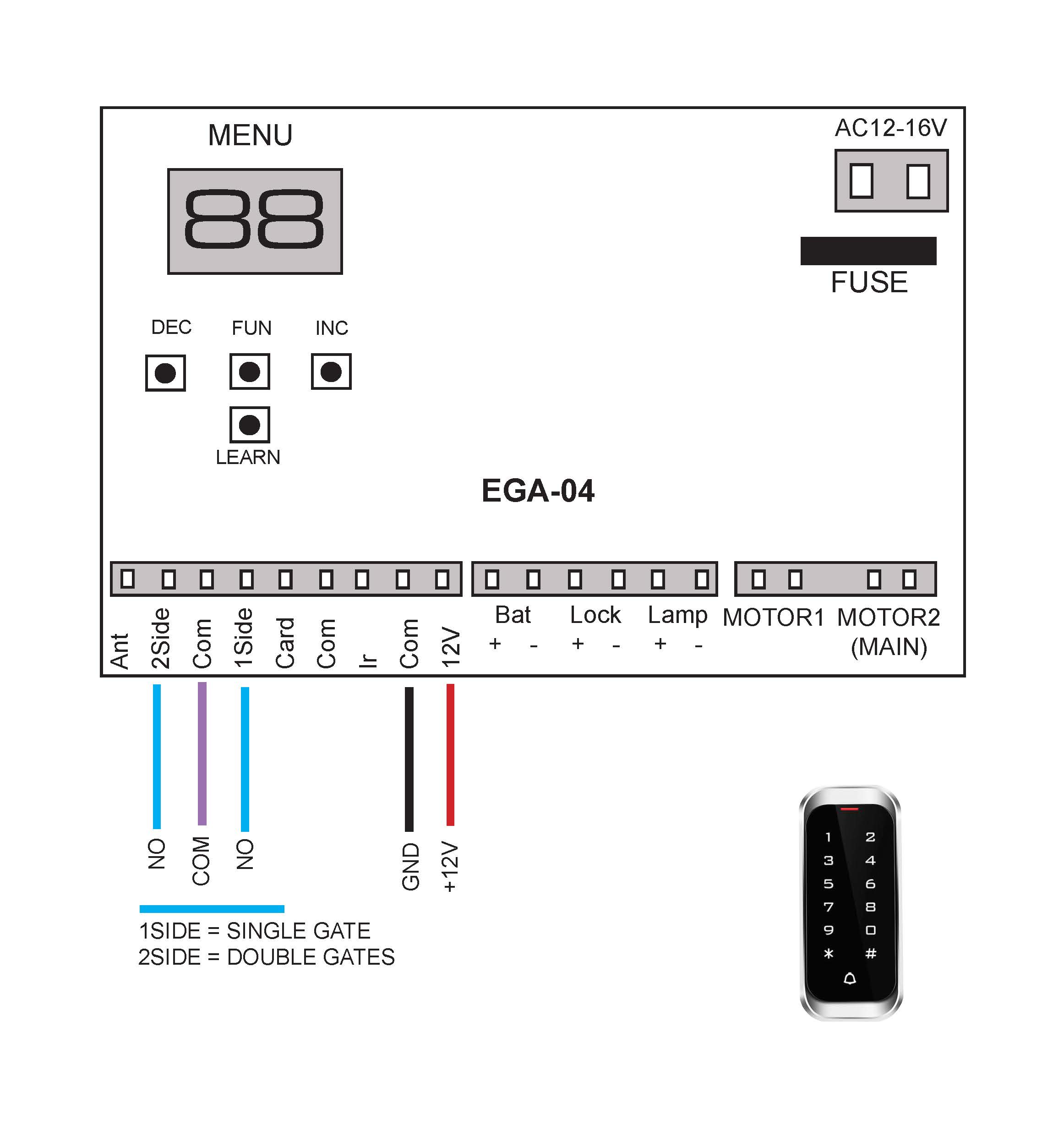
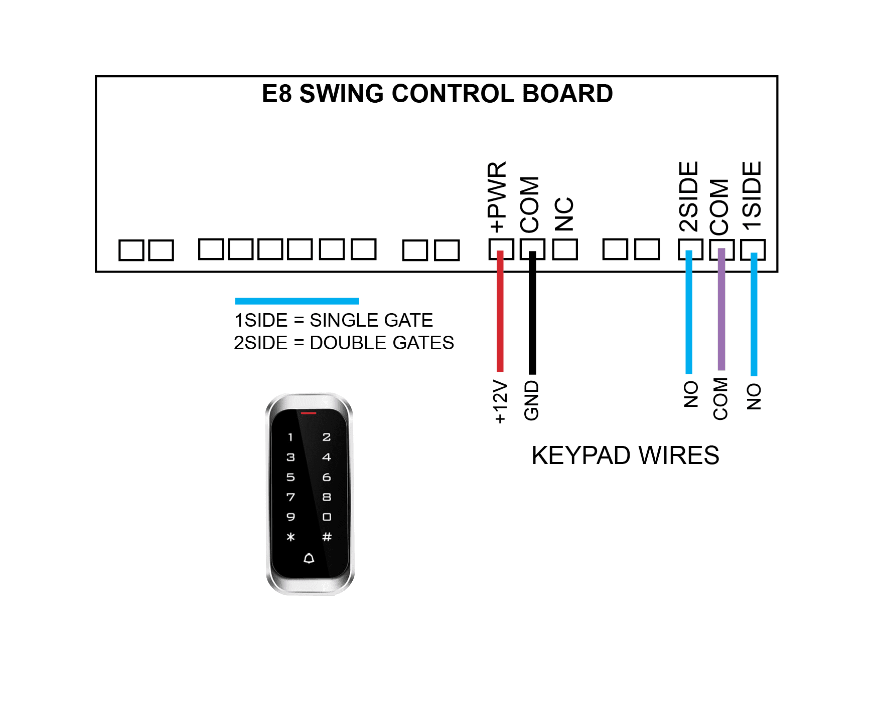
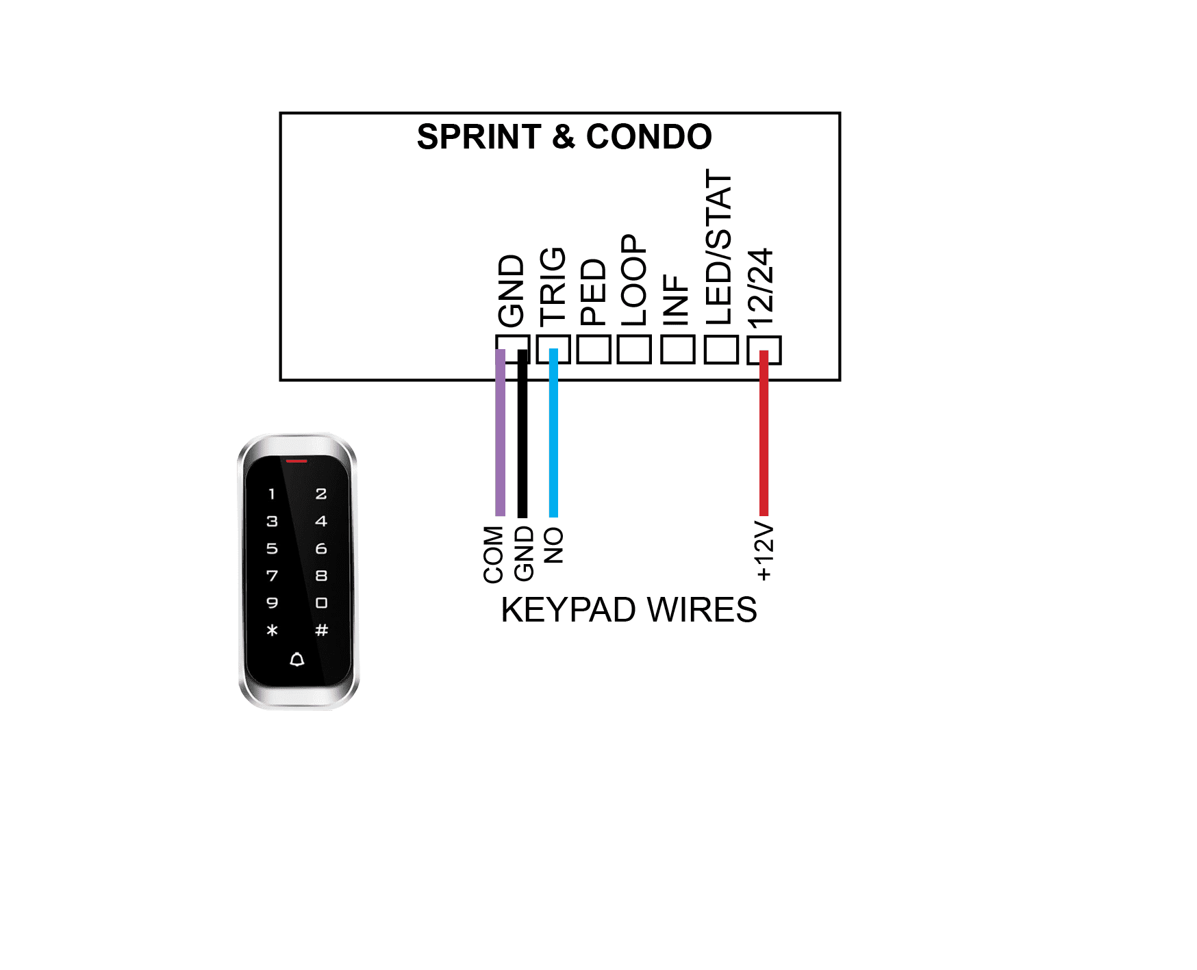
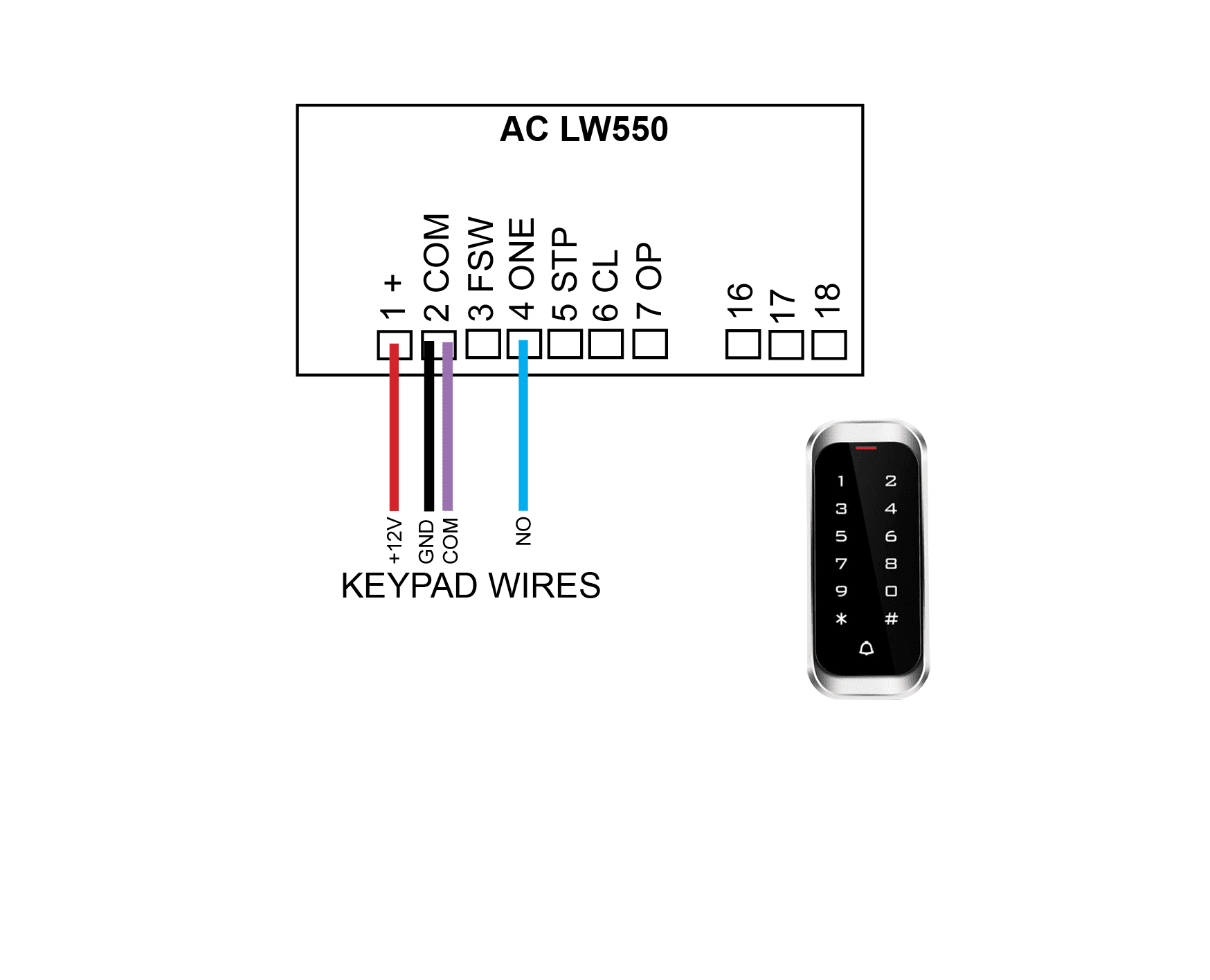
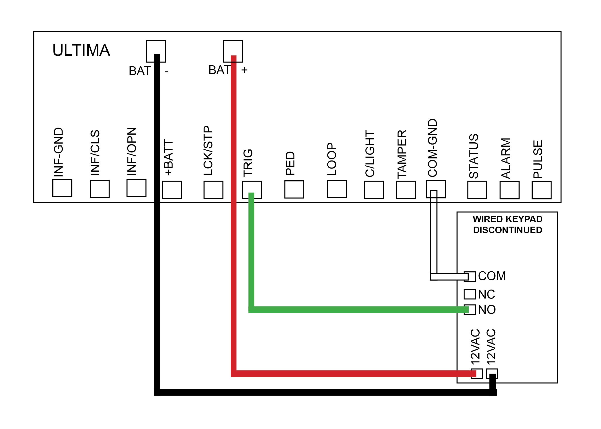
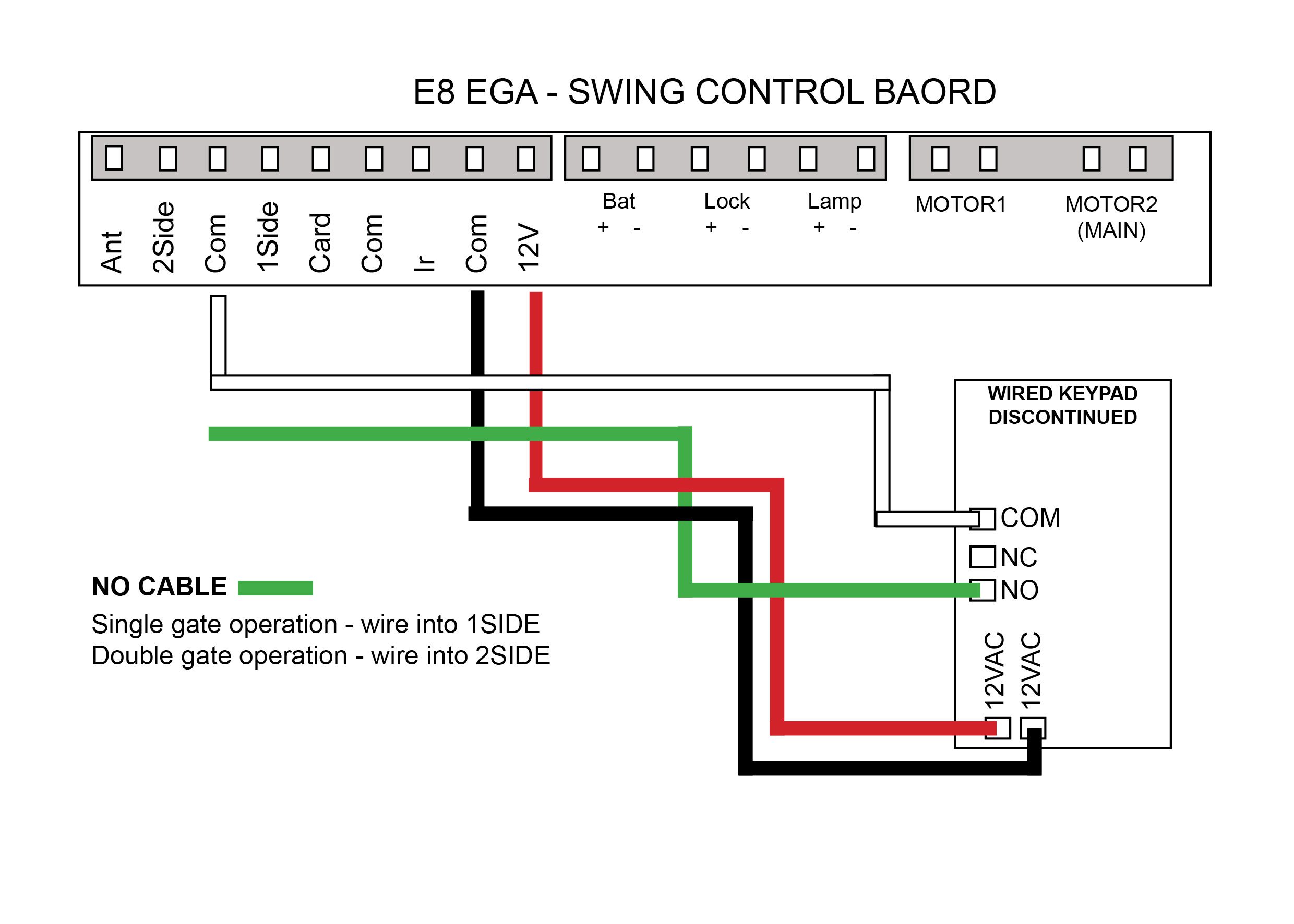
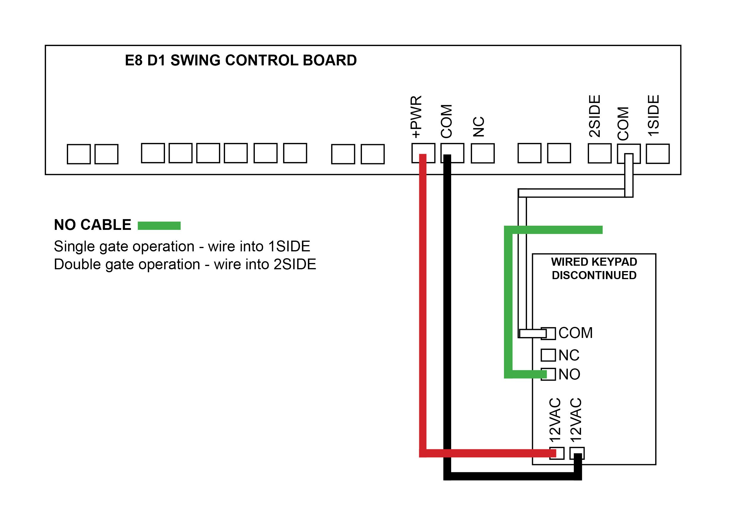
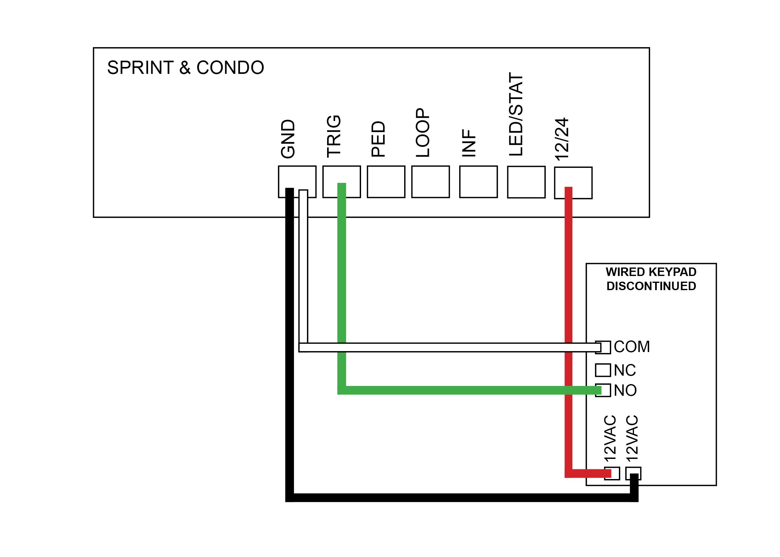
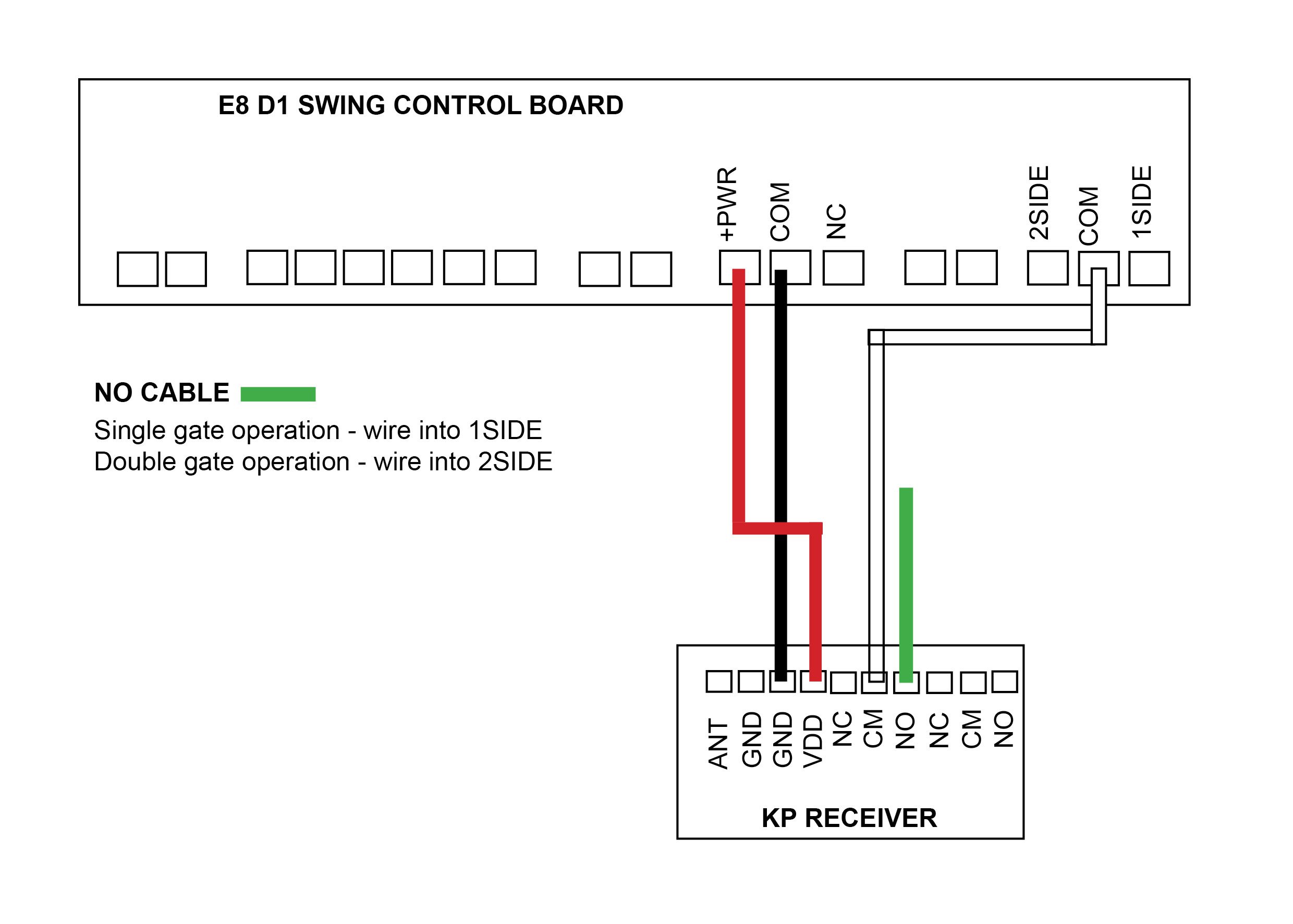
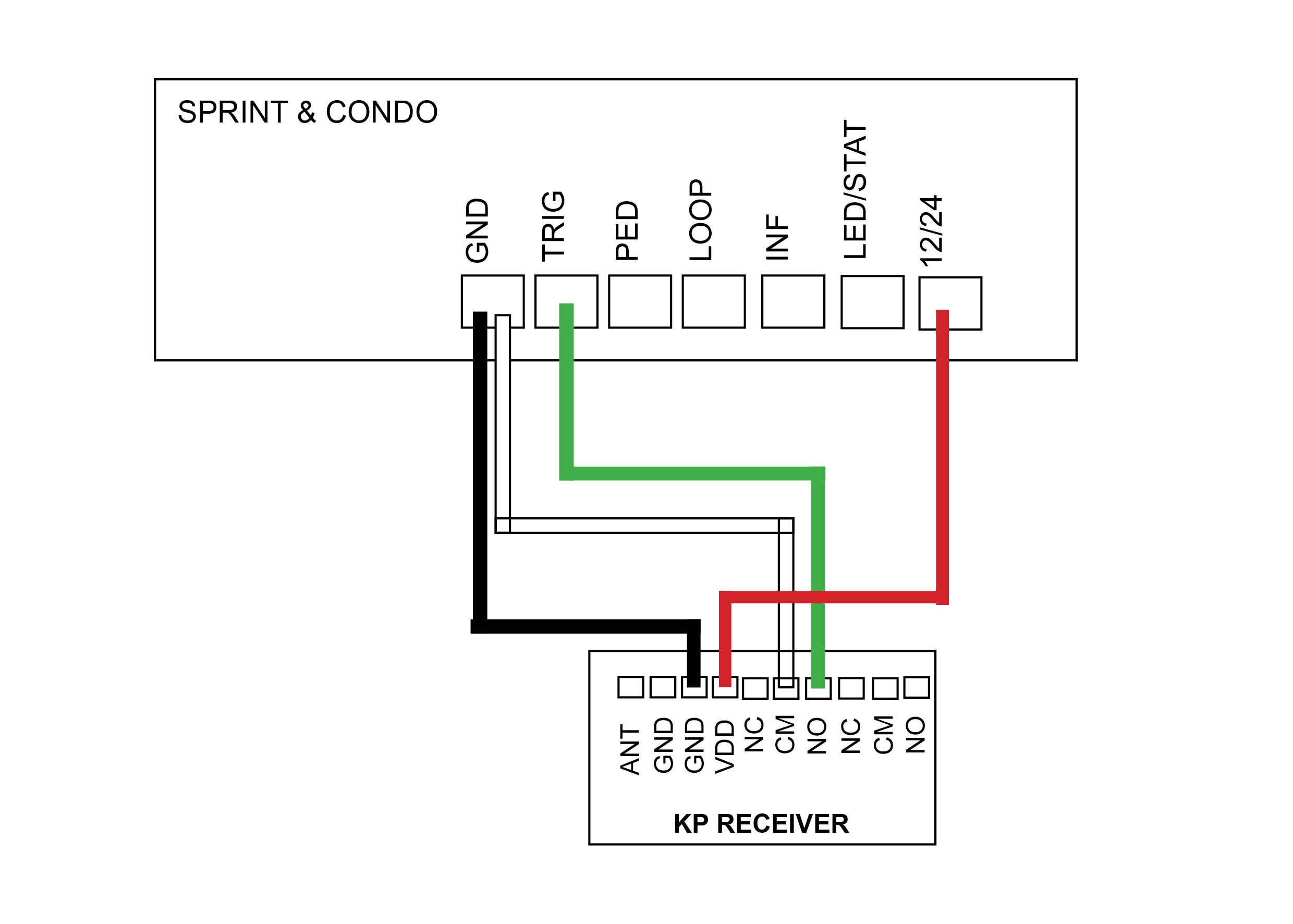
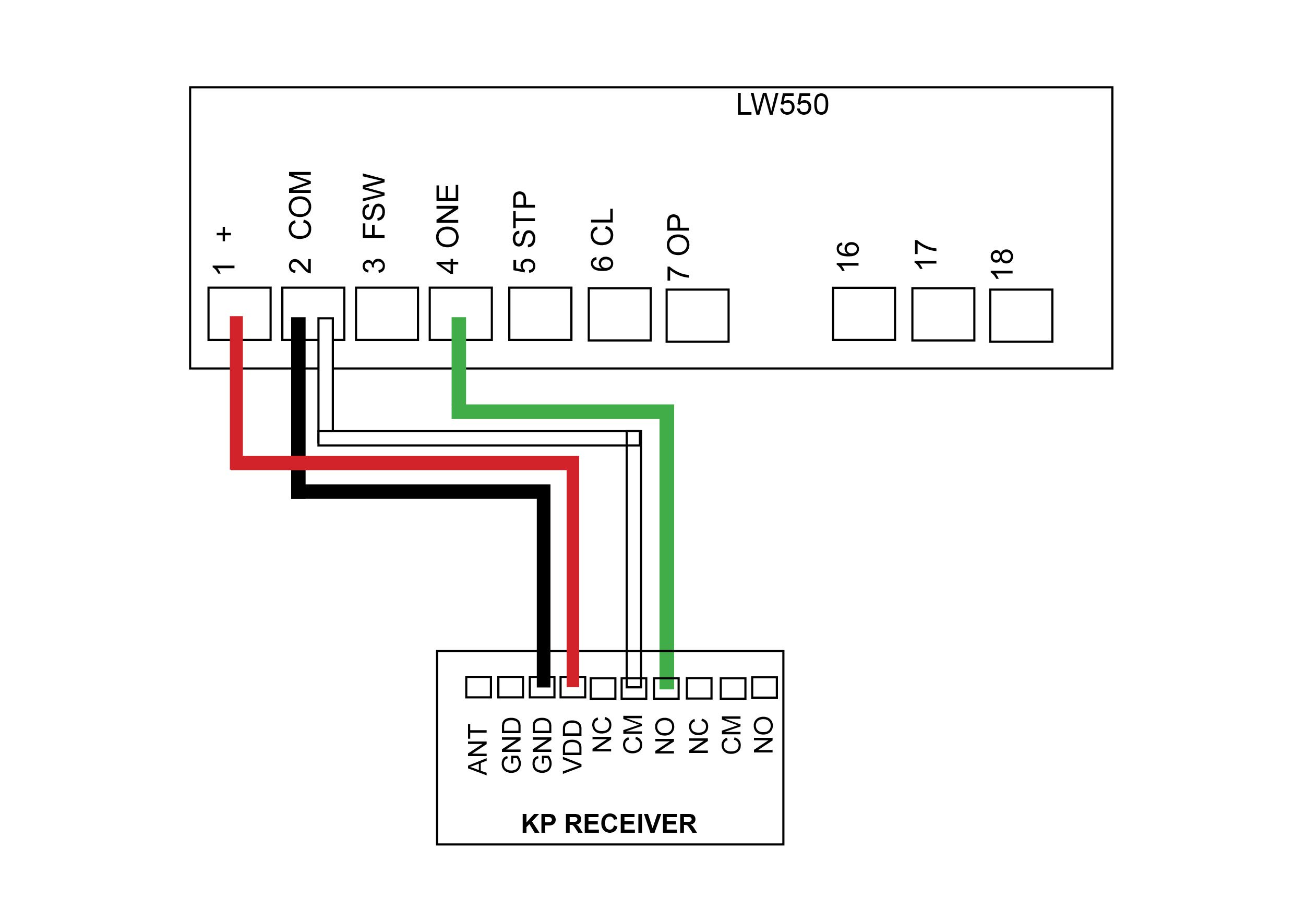
After wiring your keypad, check that it’s operational by entering the 4 digit factory code 2580.
If you have double gates you will need to follow the setup noted below for ‘Setting a delay time’.
Once gate/s are working with the factory code you can then move onto changing your master code and entering a new pin codes. You can enter over 100 pin codes.
Explaining the 3 digit user code and 4 digit pin code – When entering a new pin code you will be asked to enter in a 3 digit user code along with your 4 digit pin code. If having more than 1 pin code, the 3 digit user code must be different for each 4 digit pin code entered. The 3 digit user code is important to take note of as this is what you will need to remember if and when you need to remove your 4 digit pin code assigned to it. (eg. user code 147 & pin code 3698).
We only recommend changine the factory master code (1234) to a secure code which you must make note of if you require extra security. Failing to make note of your new master code will prevent you from being able to add or delete pin codes in the future.
How to enter a new pin code
Press # (until the red light comes on)
Enter in your 4 digit master code (factory 1 2 3 4)
Press 7
Enter 3 digit user code
Enter 4 digit pin code
Press and hold #
Now test your pin code
How to change your master code
Press # (until the red light comes on)
Enter in your 4 digit master code 1 2 3 4
Press 3
Enter your new 4 digit master code
We only recommend doing this if you require the extra security. Be sure to keep this code.
Removing a pin code
Press # (until the red light comes on)
Enter in your 4 digit master code (factory 1 2 3 4)
Press 8
Enter 3 digit user code
Enter in your 4 digit master code (factory 1 2 3 4)
Press #
Set a delay time
This may be required for double gates if the are not opening together
Press # (until the red light comes on)
Enter in your 4 digit master code (factory 1 2 3 4)
Press 6 000 1
Reset to Factory Default
Press # (untill the red light comes on)
Enter in your 4 digit master code (factory 1 2 3 4)
Press 0 (both red lights flash)
Enter in your 4 digit master code (factory 1 2 3 4)
This function comes in handy when you don’t know the 3 digit user code to “remove a pin code”, however using the factory reset will wipe all user codes and pin codes from the keypad and sets it back to 2580. When you enter your new pin code it will wipe the factory setting 2580
Back Light
When pressing #, wait till red LED light comes on
Light off Press – # (master code) 6 2800
Light on Press – # (master code) 6 2801
Light on when pincode pressed only –
press # (master code) 6 2802
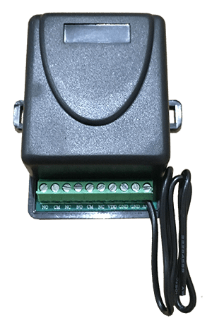
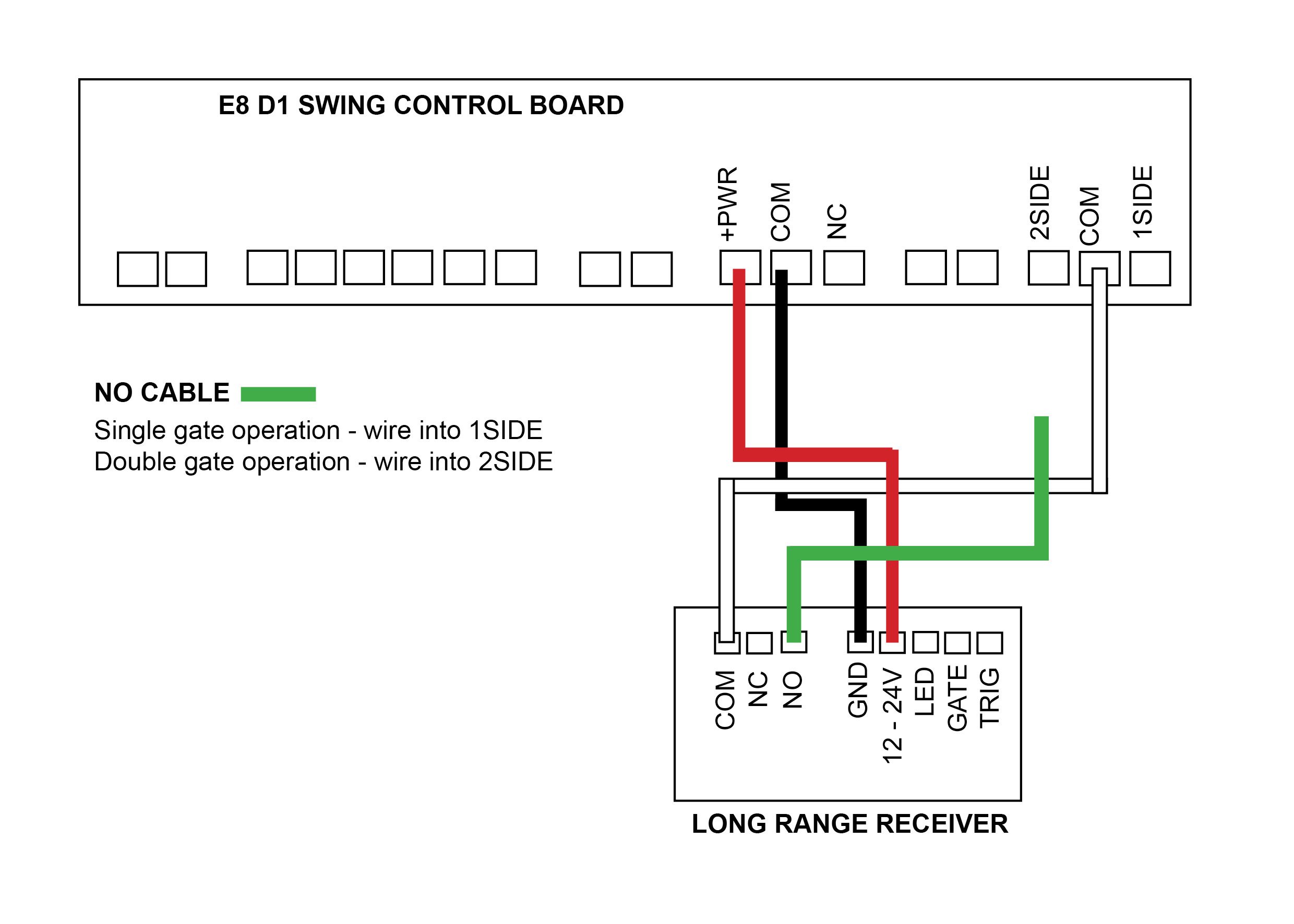
For optimum range it is advisable to place the receiver a minimum of 2
metres vertically away from the gate motor e.g. top of gate posts.
When placing the receiver outside of the control box or motor housing it is
important to use a weatherproof box with all entry points sealed. The standard
receiver housing is only splash proof and not suitable for outdoor applications. **
Make sure there are no exposed wires outside the receiver.
Placing the receiver inside the motor housing will reduce the range of the
receiver when the motor is in operation.
Range may be affected by signals transmitted from another source.
When coding remotes for use in a complex it is recommended that all
remotes be physically numbered and a record be kept.
* All dependent on line of sight to the gate and interference which may
reduce expected range. DO NOT ALTER THE ANTENNA IN ANY WAY (TUNED
LENGTH ANTENNA)
** Warranty will void if the receiver housing has been placed outside and not in a
recommended weatherproof box.


