
AC LW550 Manual (Discontinued)

AC LW550 Manual (Discontinued)

Main User
Installation Manual

Open Manual

Servicing Your Gate and Motor

Your gate and gate motor are both very important pieces of equipment.  This equipment is like a vehicle, which requires preventative maintenance especially on the coast where corrosion is a big factor.

The following MUST be done at regular intervals: (3-4 months)

  1. Check for insects, snakes and geckos in and around the PCBoard. 
  2. The gate must be lifted and the wheels that run on the rail must be checked to see that they spin freely and that the bearings haven’t collapsed, this is very important to ensure the life span of your gate motor.
  3. The gate guide wheels must be checked to see that they spin freely and ensure that they are not worn and the lock nuts are tight.
  4. Over time the gate wheels tend to bed themselves in, as a result the gate’s gear rack now rides directly on the motor’s main drive pinion gear. There should ordinarily be a 2 mm gap between the gear rack and the pinion gear. Another indication of this “binding” situation is when the motor vibrates excessively while the gate is running. This fault causes unnecessary wear and tear and will reduce the life of the operator and it must be rectified without delay. The rack can also become too loose and the gap becomes too big, which causes the pinion gear to skip the teeth on the gear rack causing a malfunction.
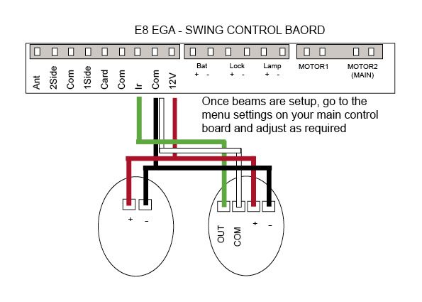
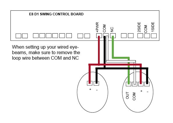
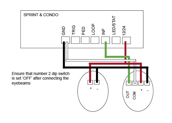
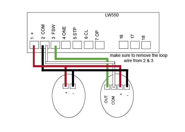
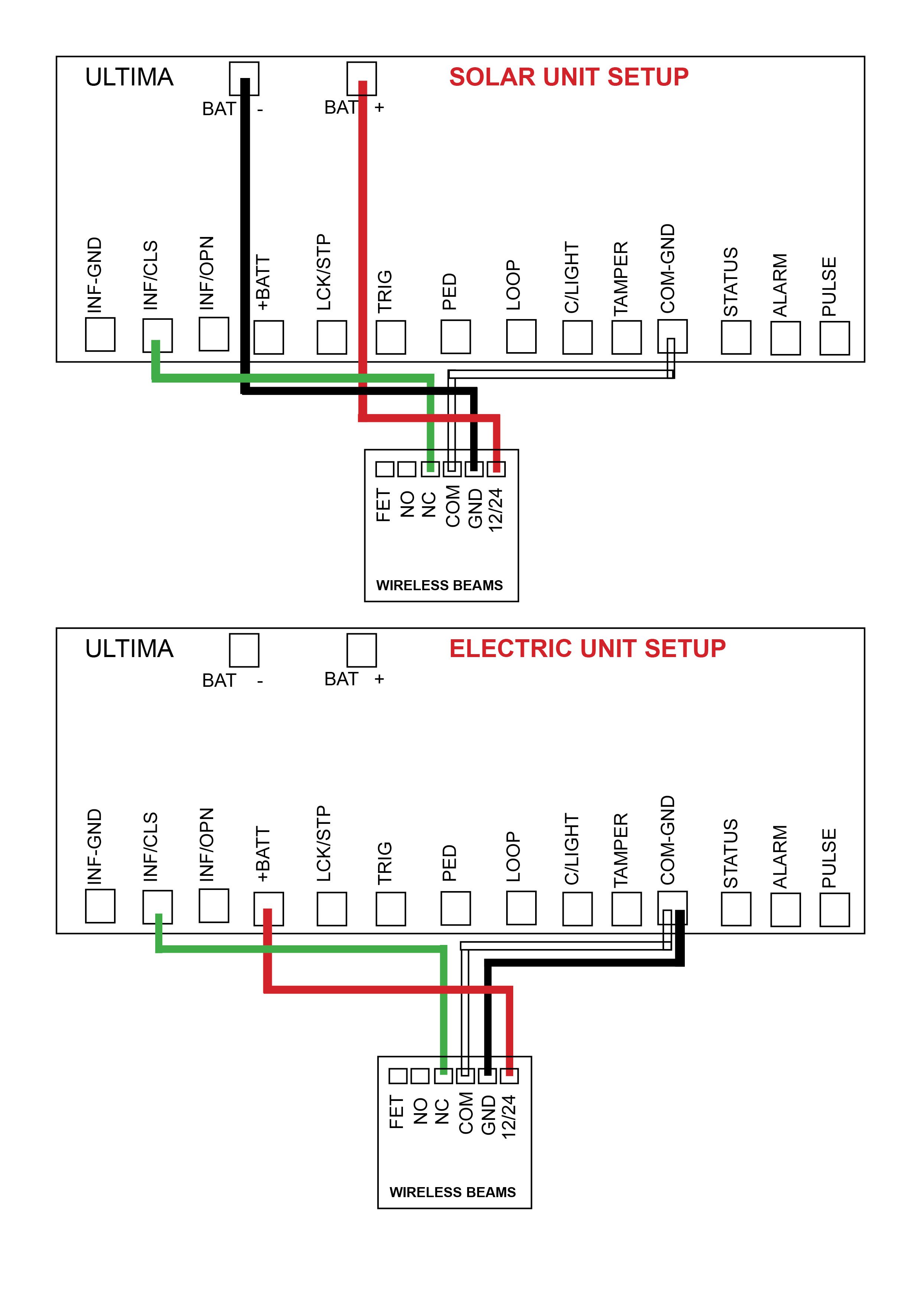
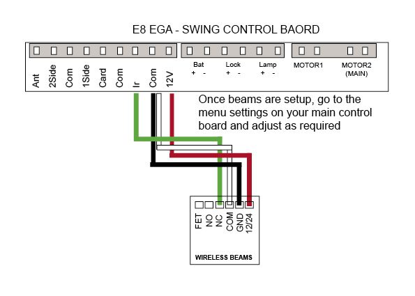
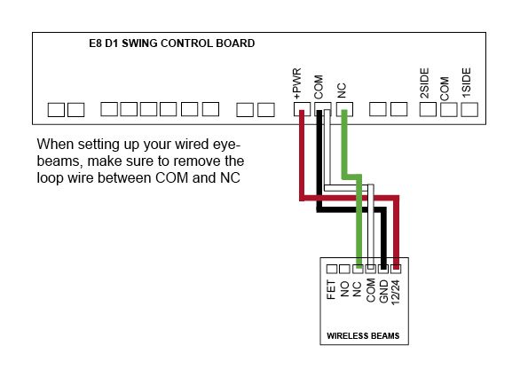
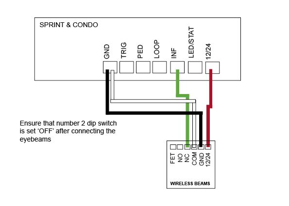
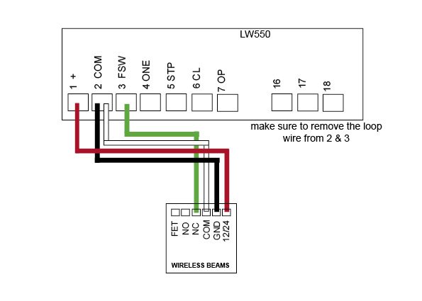
  5. If safety beams are fitted, check for any insects and ensure that there are no loose or broken wires inside the beams.
  6. Remove any plants, trees or branches that may cause an obstruction to the wheels and a blockage to the beams.
  7. Check that the operator’s foundation plate bolts are still secure.
  8. Check that the ends stops are still secure.

Continue reading

E8 Swing kit – Receiver (Discontinued)

There have been many versions of the receiver overtime, please see images
and diagrams below matching our most recent receivers.

If installing a new receiver, make sure that you have adjusted your dip switch
settings in the new receiver to match your old receiver.

Wiring Diagrams

  • E8 – EGA Swing
    Control Board

    Current

  • E8 – D1 Swing
    Control Board

    Discontinued

  • E8 – EGA Swing
    Control Board

    Current

  • E8 – D1 Swing
    Control Board

    Discontinued

  • E8 – EGA Swing
    Control Board

    Current

  • E8 – D1 Swing
    Control Board

    Discontinued

Continue reading

Electric Gate Lock

Instructions for the E8 EGA control board

EGA Control Board Menu Settings

P8 = Opening/Closing Delay Time

This setting is for Dual Swing gates. You can adjust the opening/closing delay between the two motors. This is required if you have an electric gate lock connected to the control board or if you require Motor 2 to open first and Motor 1 to close first. You can set this from 0 seconds (open and close at the same time) up to 8 seconds. Factory setting is 2 seconds and is recommended even if a gate lock is not installed.
0 = No Delay
1 = 1 second
2 = 2 seconds (factory set)
3 = 3 seconds
4 = 4 seconds
5 = 5 seconds
6 = 6 seconds
7 = 7 seconds
8 = 8 seconds

PA = Electric Lock Output Mode

This setting allows you to adjust the output to you optional electric gate lock. Factory setting is 0 which is set for NO GATE LOCK. If you install a gate lock, it is recommended you set PA to level 3 (3 seconds). This may need to be adjusted depending on your gate setup. If lock output is set to 1, the lock will activate first for 1 second before the gate starts, this is to allow time for the lock to activate.
0 = No output (factory set)
1 = 1 second
2 = 2 seconds
3 = 3 seconds
4 = 4 seconds
5 = 5 seconds
6 = 6 seconds

PC = Electric Lock Auxiliary Function

Factory setting Motor 2 will activate after 1 second to allow the gate lock to release. Setting PC to 1 will make Motor 2 reverse (close) for 0.5 seconds to help release pressure off the gate lock before allowing Motor 2 to activate.
0 = Open (factory set)
1 = Close reverse first

Instructions for the E8 D1 control board

Discontinued model

Single gate setup
Double gate setup

Continue reading

Eyebeams – wired

Wiring Diagrams

Current models

  • DACE Ultima
    Control Board

    The control board will self detect the beams. You are not required to adjust any settings.
  • E8 – EGA Swing
    Control Board

Discontinued models

  • E8 – D1 Swing
    Control Board

  • DACE Sprint/Condo
    Control Board

  • AC LW550
    Control Board

Continue reading