
Author: Joel


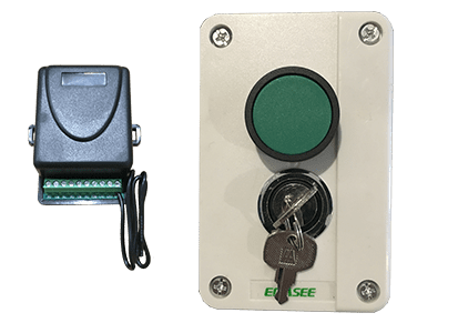
Wired Key Push Button
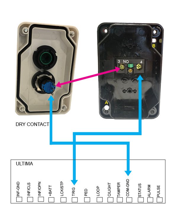
Please note that the coloured cables in our below images are for examples only and may not match the coloured cables that you will be using. When wiring up the push button, you will be able to use the key to lock and disable the button. Follow both coloured wiring instructions (pink and blue) as shown below.
When securing the blue and pink cable to the internal pins of the lock you can either secure by soldering the cable, threading cable through the hole to secure it or secure cable with a connector.
When you attach the push button unit to your post, even though the button housing is a sealed unit, we highly recommend sealing (silcone) all the way around the back housing to prevent any water or insects entering in through your screws. Also when you drill the hole for your cabling we recommend to silcone up that entry point.
We recommend every 6-12 months to do a thorough check over the push button and it’s internals to make sure there is no insect infestation and that everything is still in good working order.
Please be aware that failure to perform the recommendations above may void your warranty.
Blue cables
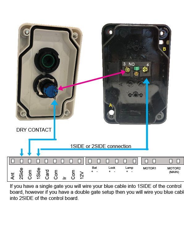
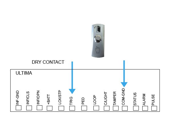
These will wire directly to the main control board, please refer to your user manual or see diagrams belowA & B Points
We recommend attaching the push button via the points shown in the diagrams below at A and B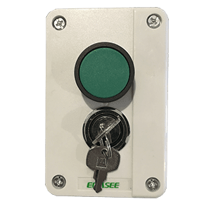
Wiring Diagrams
Current models
-

DACE Ultima
Control Board -
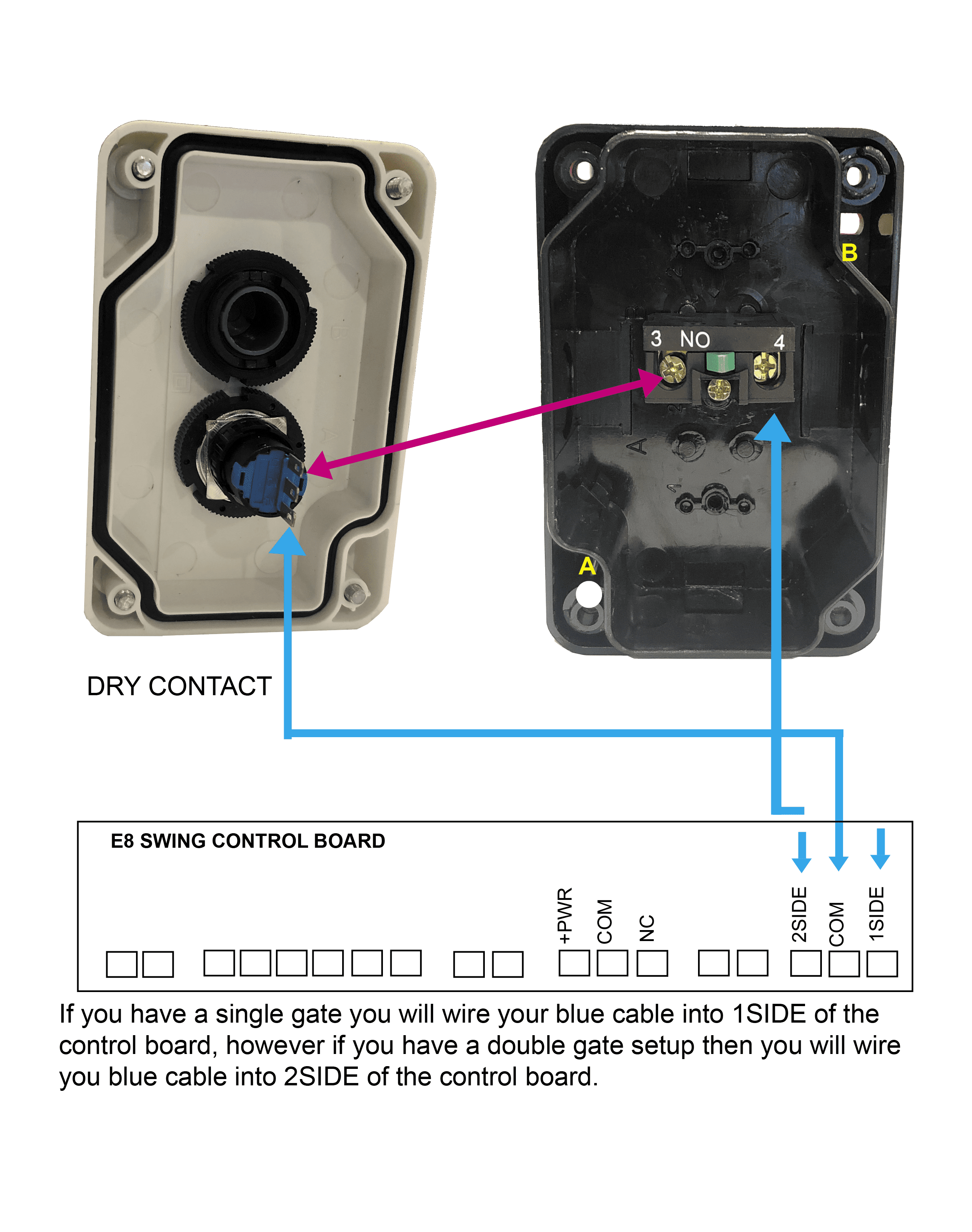
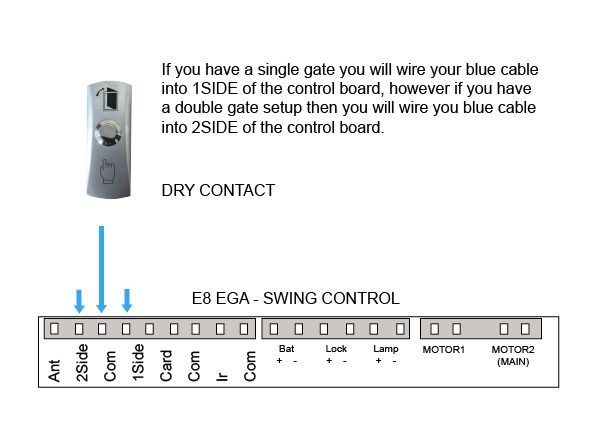
E8 – EGA Swing
Control Board
Discontinued models
-
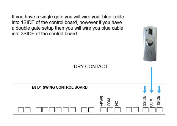
E8 – D1 Swing
Control Board -
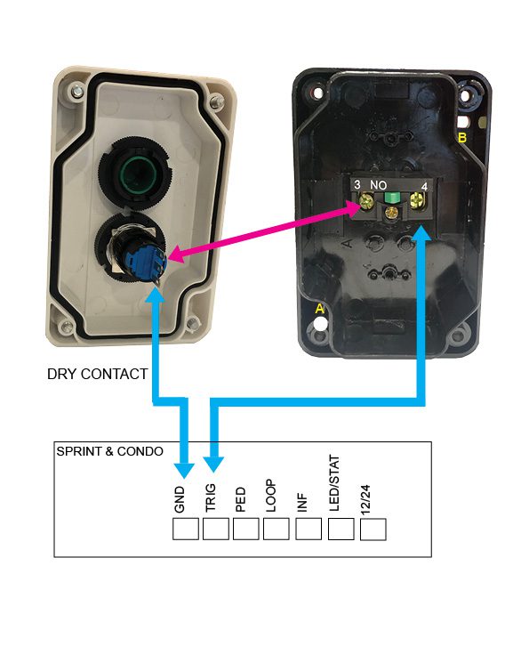
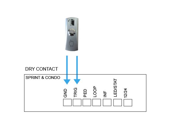
DACE Sprint/Condo Control Board
-
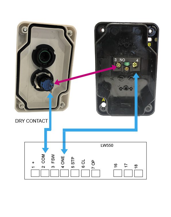
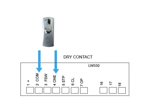
AC LW550
Control Board

Wired Push Button
Wiring Diagrams
Current models
-
DACE Ultima
Control Board -
E8 – EGA Swing
Control Board
Discontinued models
-
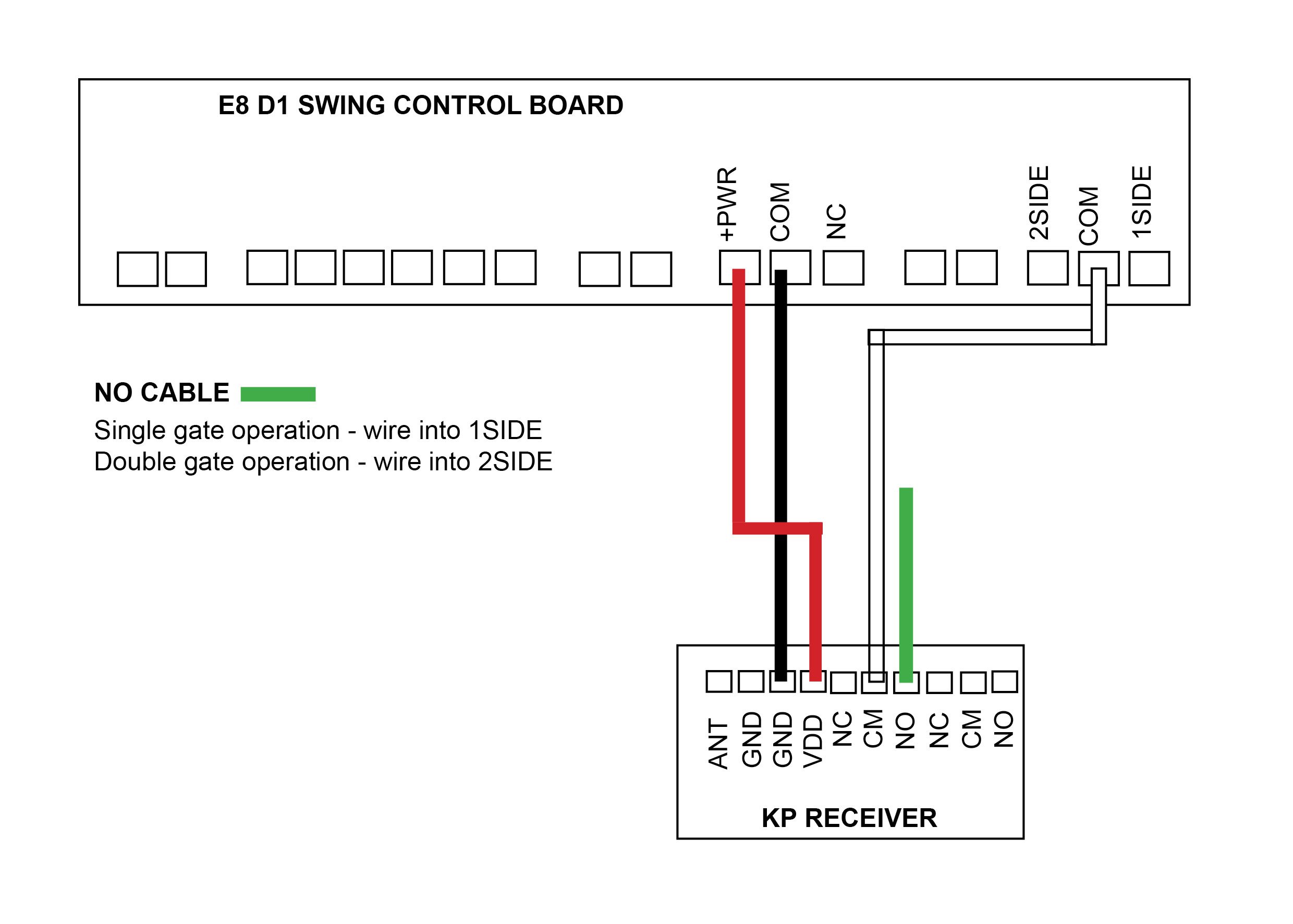
E8 – D1 Swing
Control Board -
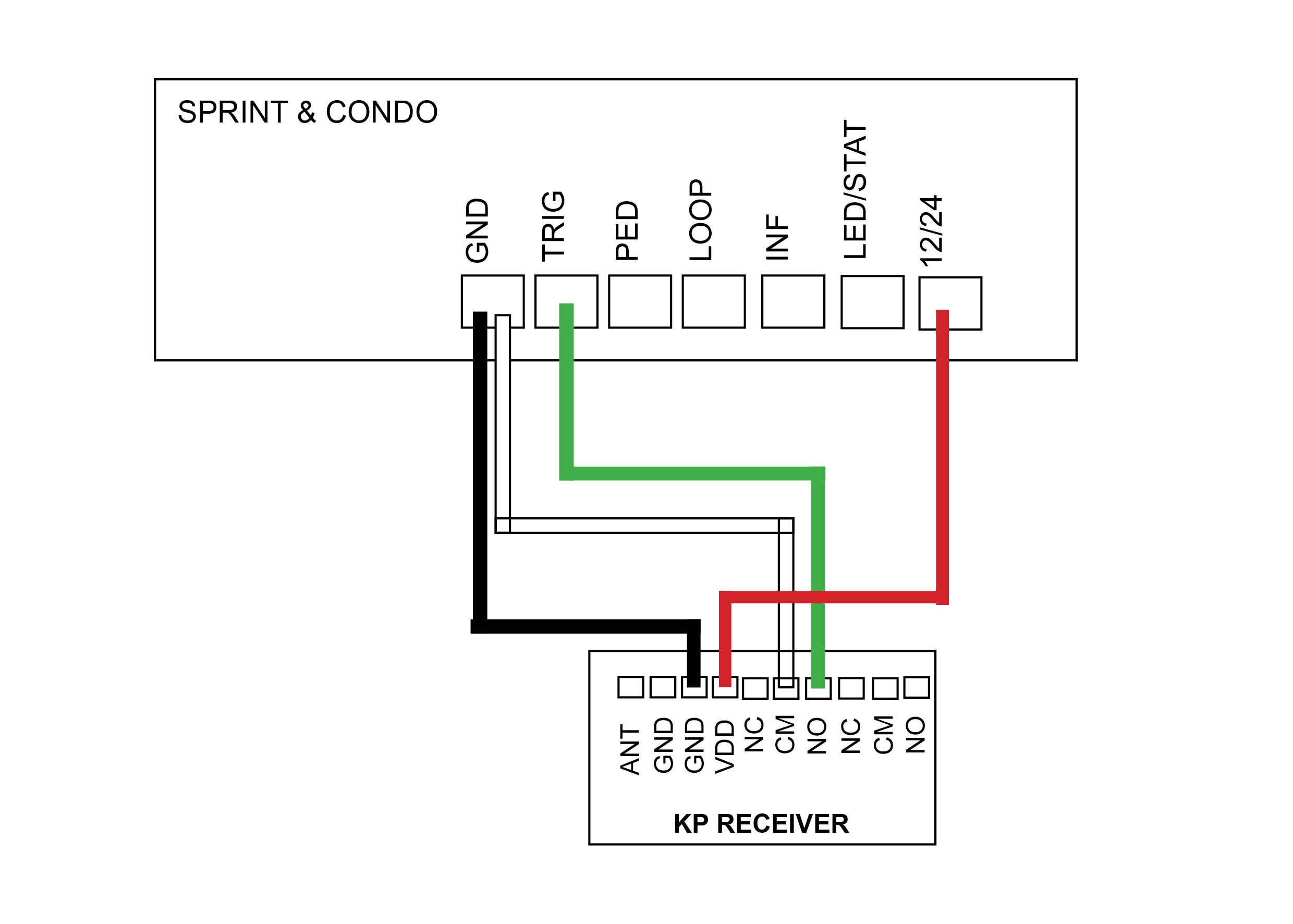
DACE Sprint/Condo
Control Board -
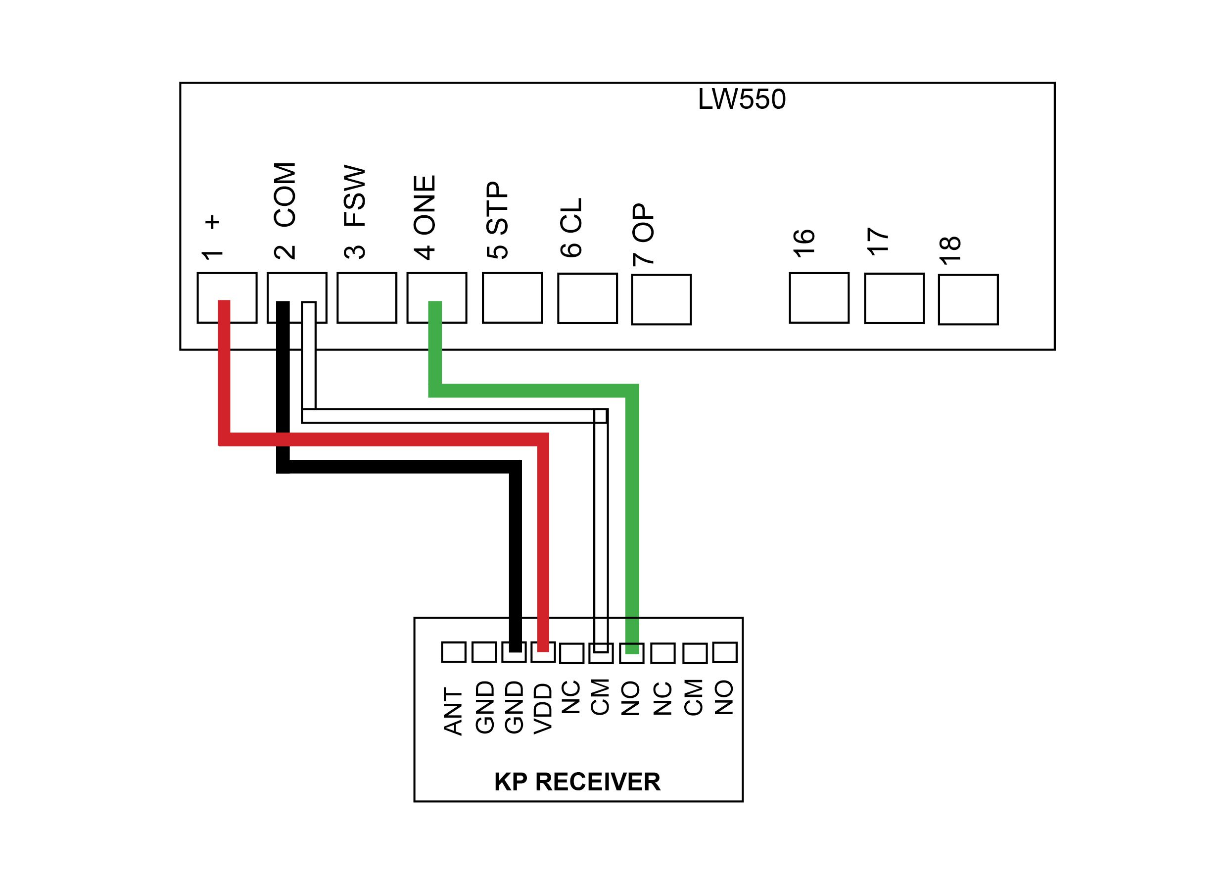
AC LW550
Control Board

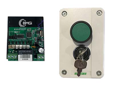
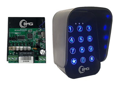
Wireless Key Push Button & KP Receiver
Pairing the KP Receiver to the wireless push button
- Press P1 on the receiver board (red LED will go solid)
- Press and hold the push button for 3 seconds (red LED will flash to say push button and receiver are paired)
Deleting KP recevier memory
- Press P2 on the receiver board for 8 seconds (red LED will go solid, keypad and receiver now unpaired)
How to pair a wireless button to the KP Receiver
Wiring Diagrams
Current models
-
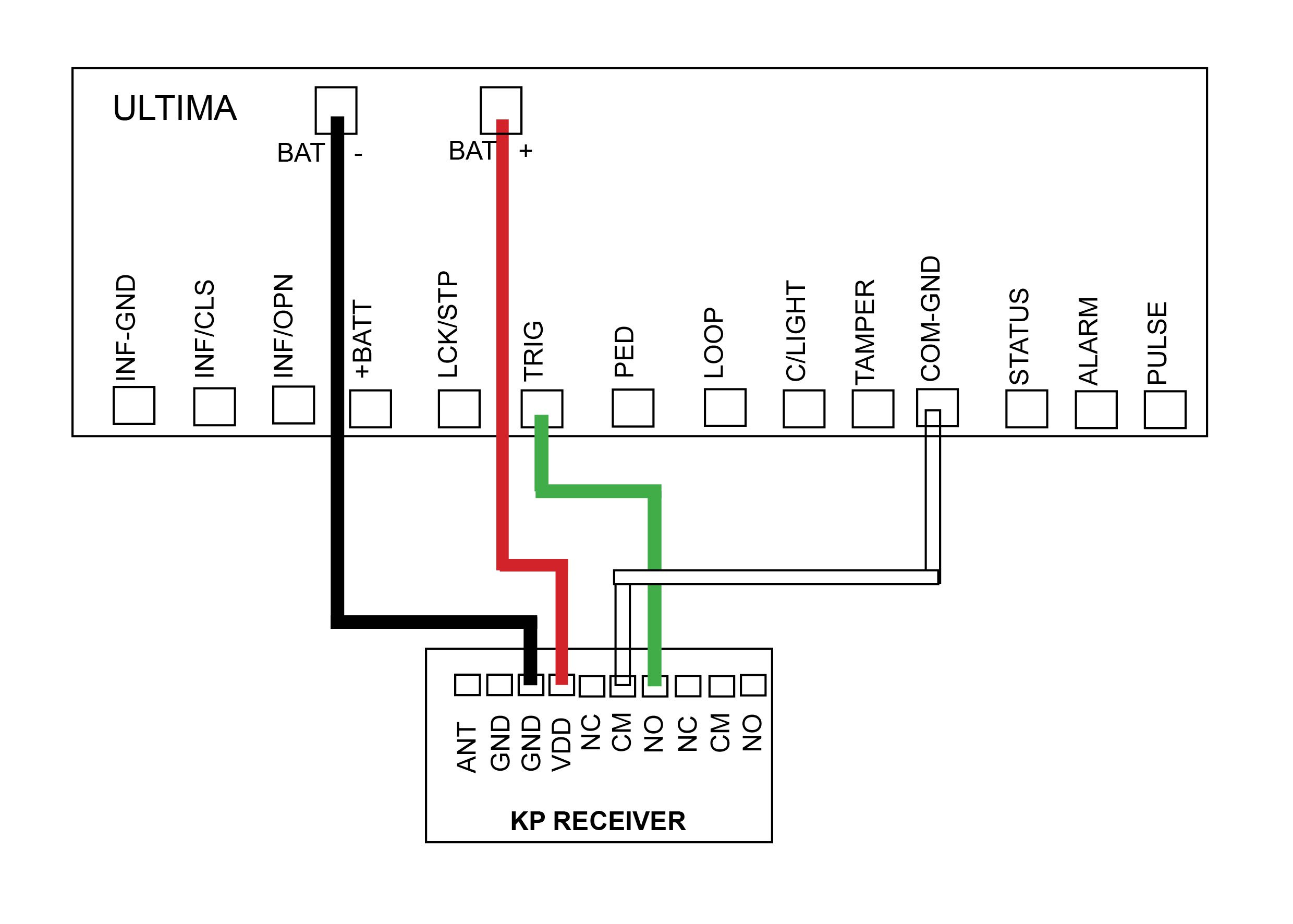
DACE Ultima
Control Board -
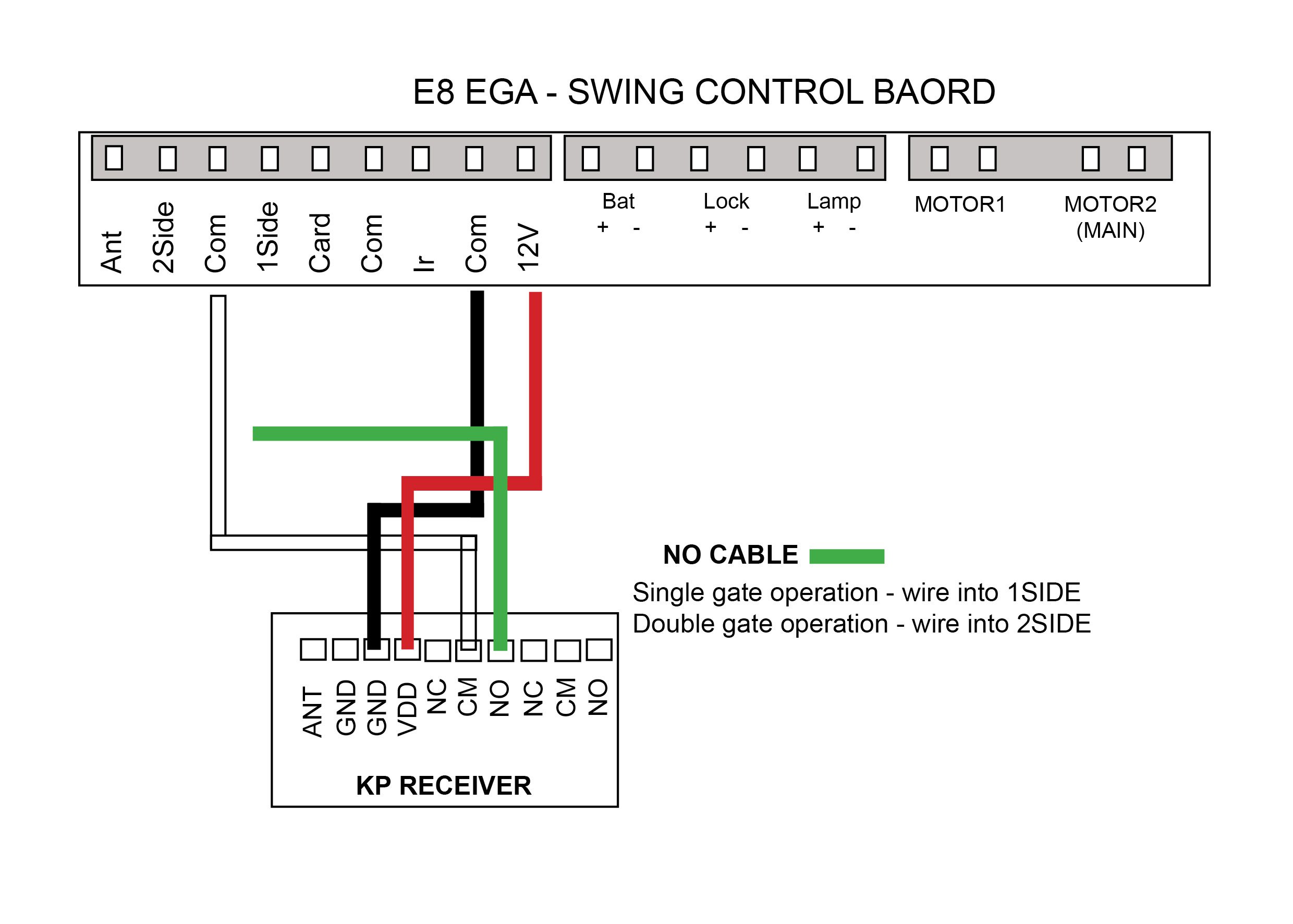
E8 – EGA Swing
Control Board
Discontinued models
-
E8 – D1 Swing
Control Board -
DACE Sprint/Condo
Control Board -
AC LW550
Control Board

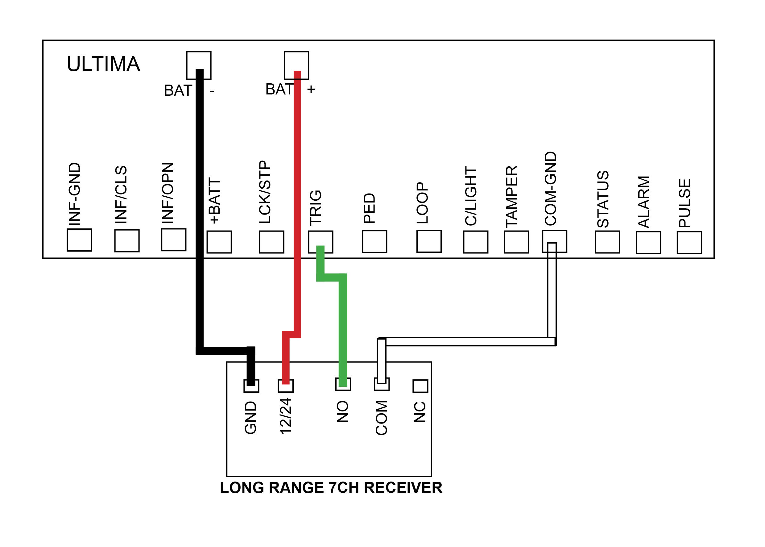
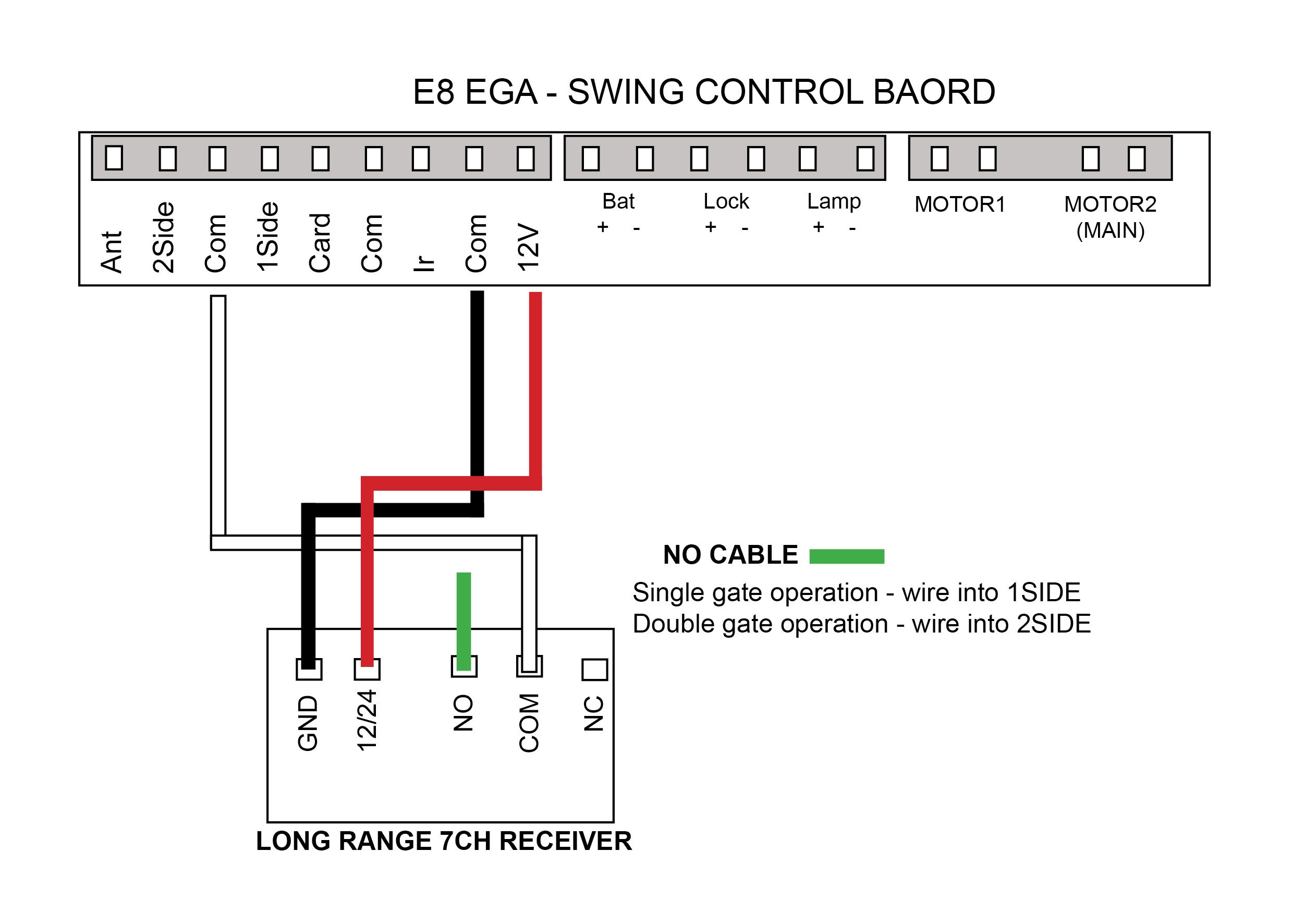
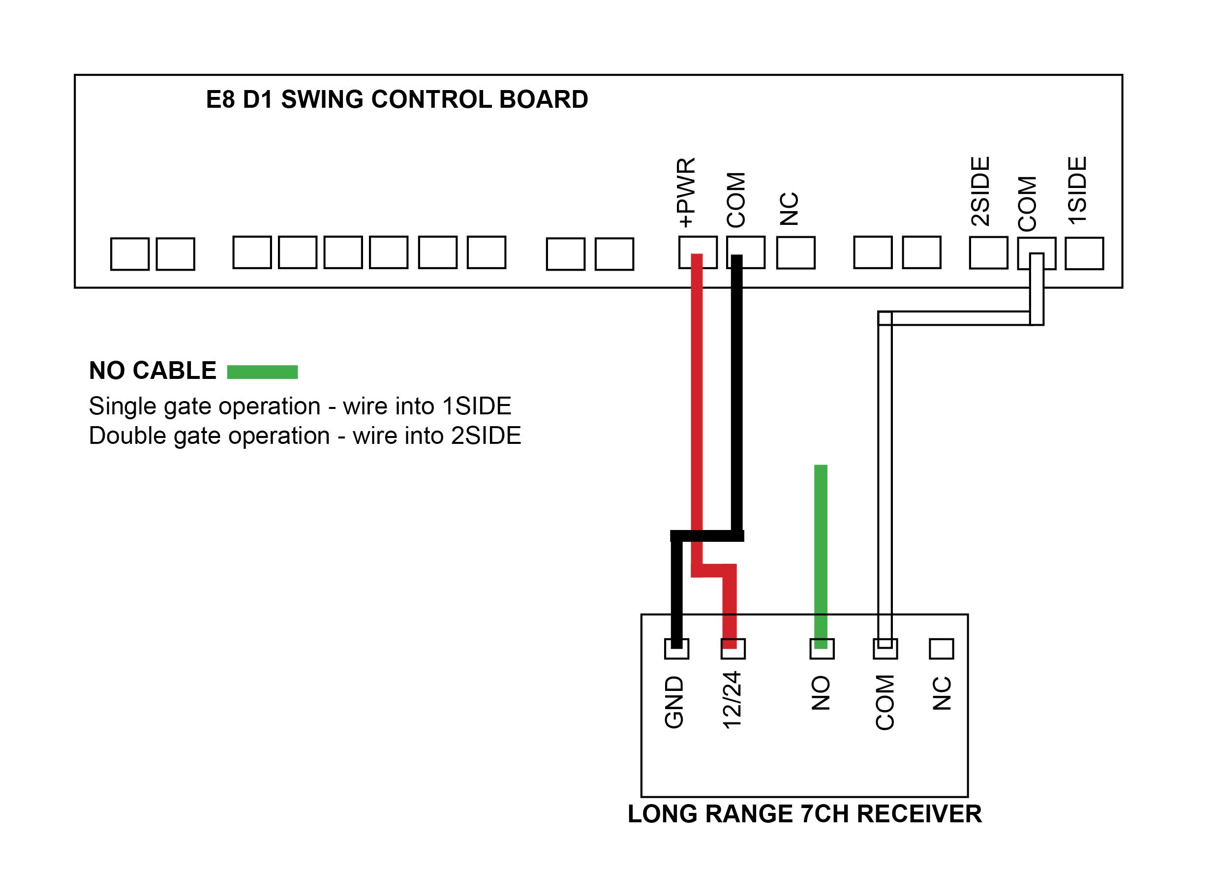
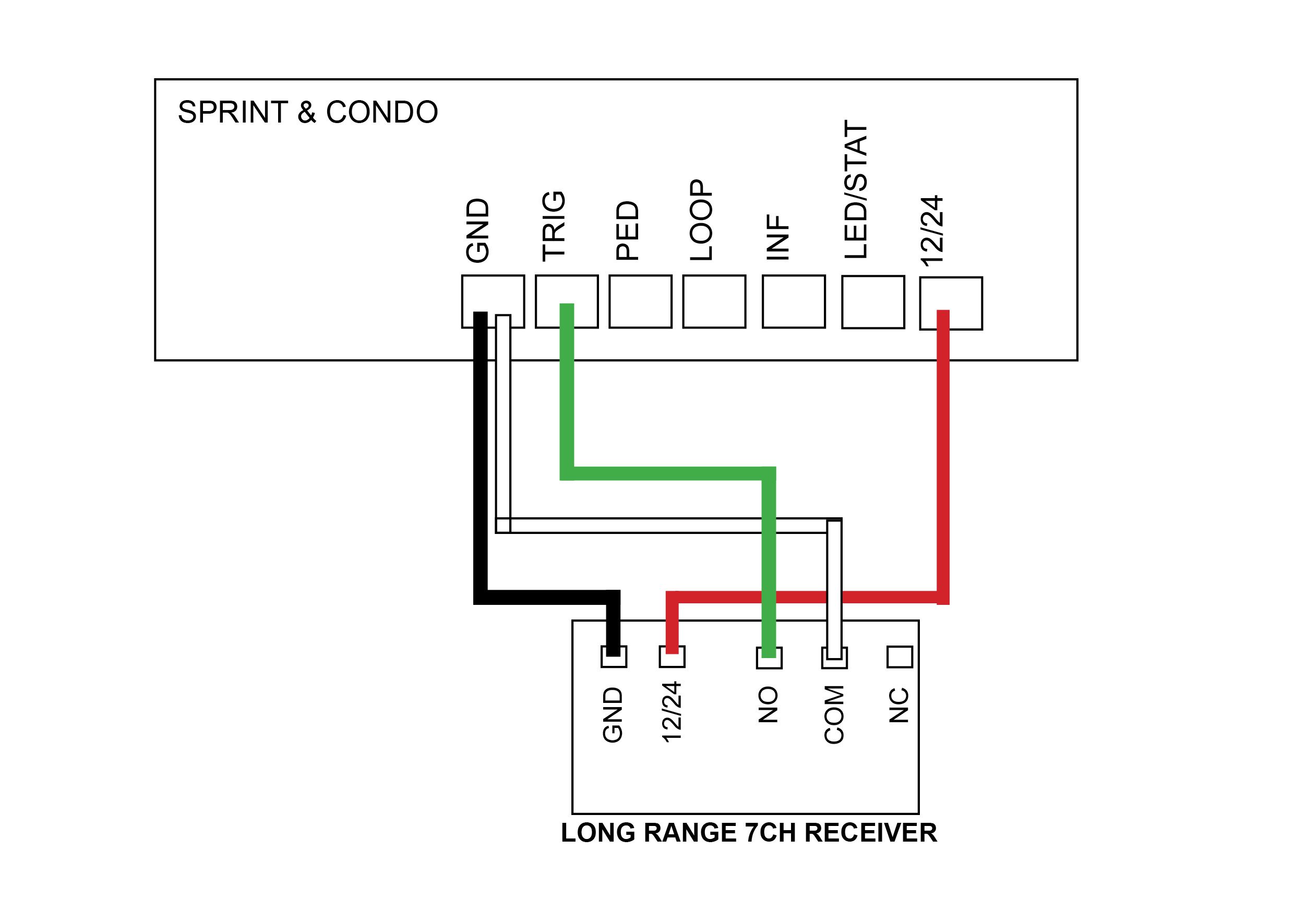
Wireless Key Push Button & LR 7CH Receiver
This receiver will have a Purple Antenna
Programming a button
- With the power connected to the receiver, place the black jumper link over the RELAY pins (if this is not already set).
- Press and hold the button to be programmed to the receiver. Wait for the green light on the receiver to flash quickly.
- While pressing the button, place the 2nd black jumper link over the REMOTE pins for 2 seconds (only) and then remove the black jumper link. Now test that the remote works.
- When finished, make sure to place the 2nd black jumper back on 1 pin only.
Erasing all buttons
Note: deleting an accessory from this receiver will delete all accessories tuned in. You will be required to tune any other items back in that you still require.
- With the power connected to the receiver, place a link over the ERASE pins.
- The LED will flash ten times and then remain on solid. Remove the link.
The buttons have now been erased from the receiver.
MANUFACTURERS RECOMMENDATIONS AND COMMENTS
- 1. For optimum range it is advisable to place the receiver a minimum of 2 metres vertically away from the gate motor e.g. top of gate posts.
- 2. When placing the receiver outside of the control box or motor housing it is important to use a weatherproof box with all entry points sealed. The standard receiver housing is only splash proof and not suitable for outdoor applications. **
- 3. Make sure there are no exposed wires outside the receiver.
- 4. Placing the receiver inside the motor housing will reduce the range of the receiver when the motor is in operation.
- 5. Range may be affected by signals transmitted from another source.
- 6. When coding remotes for use in a complex it is recommended that all remotes be physically numbered and a record be kept.
* All dependent on line of sight to the gate and interference which may reduce expected range. DO NOT ALTER THE ANTENNA IN ANY WAY (TUNED LENGTH ANTENNA)
** Warranty will void if the receiver housing has been placed outside and not in a recommended weatherproof box.
Tuning a remote to the long range receiver – Purple Antenna
Wiring Diagrams
Current models
-
DACE Ultima
Control Board -
E8 – EGA Swing
Control Board
Discontinued models
-
E8 – D1 Swing
Control Board -
DACE Sprint/Condo
Control Board -
AC LW550
Control Board

Wireless Keypad
We do recommend that you change the factory program code (0000) to a secure code which you must make note of. Failing to make note of your new program code will prevent you from being able to add or delete pin codes in the future. You would then be required to perform the ‘Keypad reset’.
Factory pin code in the keypad to start off with is 1111#. When entering in your first pin code the factory pin code will be wiped.
Changing the 4 digit ‘program code’ (0000)
- Enter program code = 0 0 0 0 *
- Press 6 9 #
- Enter new 4 digit program mode code #
Setting up a 4 digit pin code in your keypad
- Enter program code (Factory 0000) then press *
- Press 0 1 #
- Enter your pin code = ? ? ? ? # (pin code now entered)
Deleting keypad from recevier
- With the power connected to the receiver, place a link over the ERASE pins.
- The LED will flash ten times and then remain on solid.
- Remove the link. The remote buttons have now been erased from the receiver.
Delete a single pin code from the keypad
- Enter program code (Factory 0000) then press *
- Press 5 8 #
- Enter 4 digit pin number that you want to delete (keypad will give 1 long beep followed by a short beep to indicate the pin code deleted)
Erasing all pin codes from the keypad
- Enter your program code (Factory is 0000) then press *
- Press 0 0 #
- Now all pin codes will be wiped and set back to the factory pin code 1111#
Battery test
- Enter program code (Factory 0000) then press *
- Press 8 9 # (battery is OK with a long beep or if battery is low there will be a short beep and the red LED indicator will show)
Turn off/on keypad backlight
- Enter program code (Factory 0000) then press *
- Press 3 9 #
Keypad resetting
- Remove keypad from weather shield
- Awake keypad (press any button)
- While the keypad alarm is going off, press the reset button located on top of the keypad for 5 seconds until all LED lights come on
- Now release the reset button, resetting is now complete (keypad codes will be cleared)
- Place back into the weather shield
Security lock
Keypad will allow three attempts of a wrong pin code entry. After the third wrong entry the keypad will be locked for 2 minutes with 3 beeps and the red LED light will come on. 2 minutes later, the keypad would have one beep sound and the red LED indicator will go off to indicate the keypad is unlock.
Did your keypad come with a receiver? If yes then follow the links below for wiring instructions
Watch our videos below to help with programming
and tuning your keypad to the correct device
How to add a pin number
How to tune change your programming code
How to tune your keypad to the KP Receiver
Tuning your keypad to the E8 EGA Control Board
How to tune your keypad to the LR Receiver
How to tune your keypad to the Ultima (Electric)

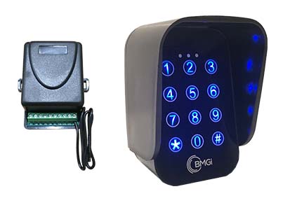
Wireless Keypad & KP Receiver
We do recommend that you change the factory program code (0000) to a secure code which you must make note of. Failing to make note of your new program code will prevent you from being able to add or delete pin codes in the future. You would then be required to perform the ‘Keypad reset’.
Factory pin code in the keypad to start off with is 1111#. When entering in your first pin code the factory pin code will be wiped.
Pairing the receiver to the wireless keypad
You must have a 4digit pin number setup in your keypad before pairing
- Press P1 on the receiver board (red LED will go solid)
- Enter your pin code = ? ? ? ? # (red LED will flash to say keypad and receiver are paired)
Changing the 4 digit ‘program code’ (0000)
- Enter program code = 0 0 0 0 *
- Press 6 9 #
- Enter new 4 digit program mode code #
Deleting KP recevier memory
- Press P2 on the receiver board for 8 seconds (red LED will go solid, keypad and receiver now unpaired)
Setting up a 4 digit pin code in your keypad
- Enter program code (factory 0000) then press *
- Press 0 1 #
- Enter your pin code = ? ? ? ? # (pin code now entered)
Delete a single pin code from the keypad
- Enter program code (factory 0000) then press *
- Press 5 8 #
- Enter 4 digit pin number that you want to delete (keypad will give 1 long beep followed by a short beep to indicate the pin code deleted)
Turn off/on keypad backlight
- Enter program code (factory 0000) then press *
- Press 3 9 #
Erasing all pin codes from the keypad
- Enter your program code (Factory is 0000) then press *
- Press 0 0 #
- Now all pin codes will be wiped and set back to the factory pin code 1111#
Battery test
- Enter program code (factory 0000) then press *
- Press 8 9 # (battery is OK with a long beep or if battery is low there will be a short beep and the red LED indicator will show)
Keypad resetting
- Remove keypad from weather shield
- Awake keypad (press any button)
- While the keypad alarm is going off, press the reset button located on top of the keypad for 5 seconds until all LED lights come on
- Now release the reset button, resetting now complete (keypad codes will be cleared)
- Place back into the weather shield
Security lock
Keypad will allow three attempts of a wrong pin code entry. After the third wrong entry the keypad will be locked for 2 minutes with 3 beeps and the red LED light will come on. 2 minutes later, the keypad would have one beep sound and the red LED indicator will go off to indicate the keypad is unlocked.
How to tune the wireless keypad to the KP Receiver
How to tune change your programming code
How to add a pin number
Wiring Diagrams
Current models
-
DACE Ultima
Control Board -
E8 – EGA Swing
Control Board
Discontinued models
-
E8 – D1 Swing
Control Board -
DACE Sprint/Condo
Control Board -
AC LW550
Control Board

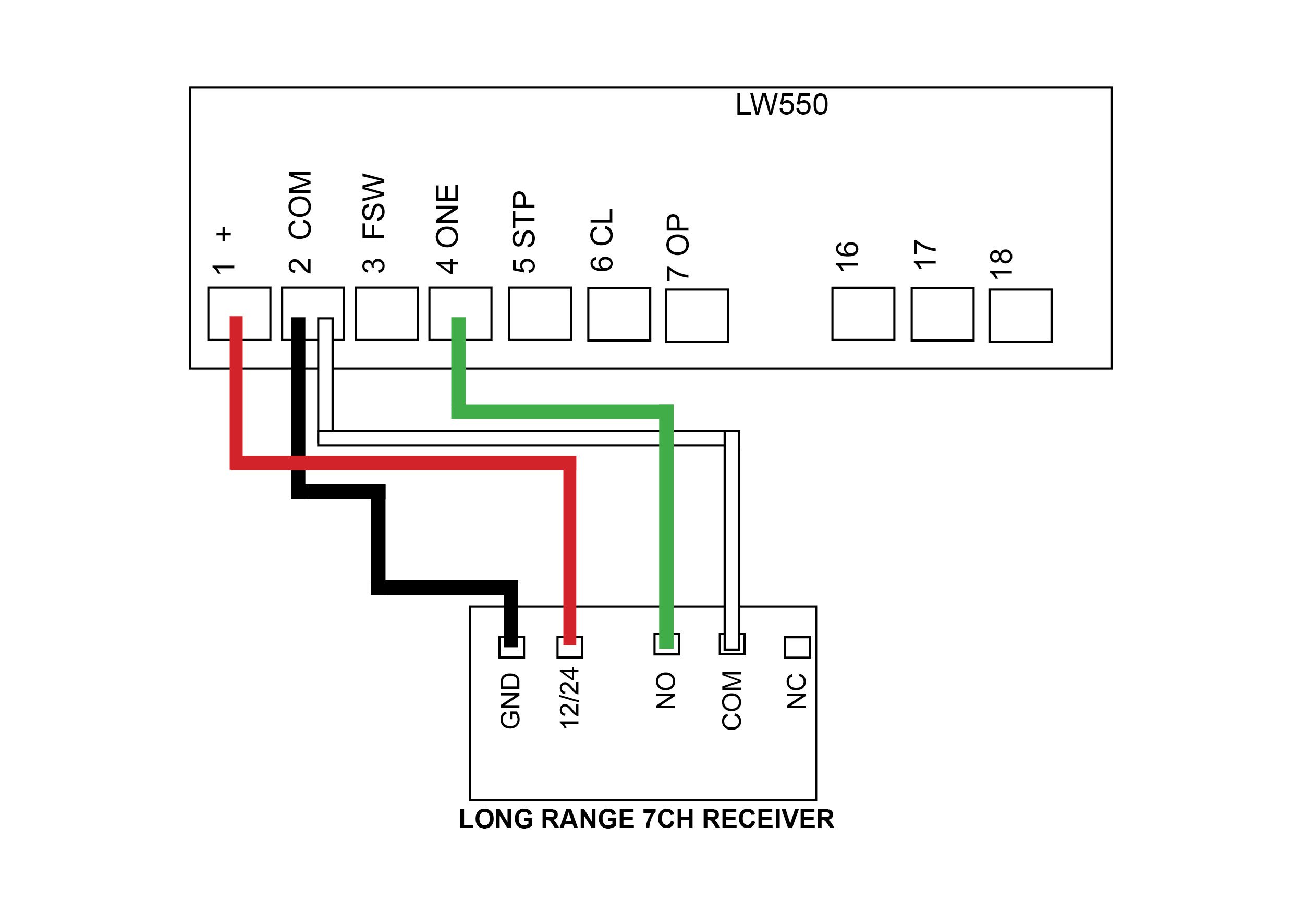
Wireless Keypad & LR 7CH Receiver
We do recommend that you change the factory program code (0000) to a secure code which you must make note of. Failing to make note of your new program code will prevent you from being able to add or delete pin codes in the future. You would then be required to perform the ‘Keypad reset’.
Factory pin code in the keypad to start off with is 1111#. When entering in your first pin code the factory pin code will be wiped.
Pairing the receiver to the wireless keypad
You must have a 4digit pin number setup in your keypad before pairing
- With the power connected to the receiver, make sure one black jumper link is over the RELAY pins (if this is not already set).
- Enter your 4 digit pin code = ? ? ? ? # (you only have a few seconds to pair the 2 together). Wait for the green light on the receiver to flash quickly then place the 2nd black jumper link over the REMOTE pins for 2 seconds (only) and then remove the black jumper link. Now test that the keypad works.
- When finished, make sure to place the 2nd black jumper back on 1 pin only.
Changing the 4 digit ‘program code’ (0000)
- Enter program code (factory 0000) then press *
- Press 6 9 #
- Enter new 4 digit program mode code #
Deleting keypad from recevier
Note: deleting an accessory from this receiver will delete all accessories tuned in. You will be required to tune any other items back in that you still require.
- With the power connected to the receiver, place a link over the ERASE pins.
- The LED will flash ten times and then remain on solid.
- Remove the link. The keypad and all other accessories tuned the receiver have now been erased.
Setting up a 4 digit pin code in your keypad
- Enter program code (factory 0000) then press *
- Press 0 1 #
- Enter your pin code = ? ? ? ? # (pin code now entered)
Turn off/on keypad backlight
- Enter program code (factory 0000) then press *
- Press 3 9 #
Delete a single pin code from the keypad
- Enter program code (factory 0000) then press *
- Press 5 8 #
- Enter 4 digit pin number that you want to delete (keypad will give 1 long beep followed by a short beep to indicate the pin code deleted)
Erasing all pin codes from the keypad
- Enter your program code (Factory is 0000) then press *
- Press 0 0 #
- Now all pin codes will be wiped and set back to the factory pin code 1111#
Battery test
- Enter program code (factory 0000) then press *
- Press 8 9 # (battery is OK with a long beep or if battery is low there will be a short beep and the red LED indicator will show)
Keypad resetting
- Remove keypad from weather shield
- Awake keypad (press any button)
- While the keypad alarm is going off, press the reset button located on top of the keypad for 5 seconds until all LED lights come on
- Now release the reset button, resetting now complete (keypad codes will be cleared)
- Place back into the weather shield
Security lock
Keypad will allow three attempts of a wrong pin code entry. After the third wrong entry the keypad will be locked for 2 minutes with 3 beeps and the red LED light will come on. 2 minutes later, the keypad would have one beep sound and the red LED indicator will go off to indicate the keypad is unlock.
How to tune the wireless keypad to the KP Receiver
How to tune change your programming code
How to add a pin number
Wiring Diagrams
Current models
-
DACE Ultima
Control Board -
E8 – EGA Swing
Control Board
Discontinued models
-
E8 – D1 Swing
Control Board -
DACE Sprint/Condo
Control Board -
AC LW550
Control Board